Got a Cobblebot kit in your closet? Know someone who does? A good proportion of “news” on the net which includes the name “Cobblebot” is completely free of useful information, although there are some useful tips out there. Here’s my January 2020 brain dump of what’s going on with my Cobblebot.
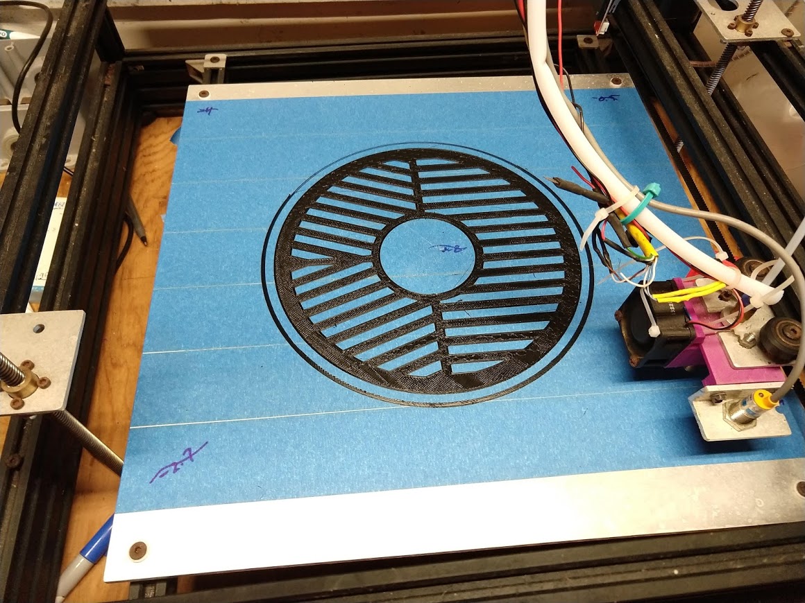
On January 1st, 2020, I 3D printed an ABS Bahtinov mask for a Celestron 8” SC Telescope on my Cobblebot 3D Printer. I did it in one try, thanks to my 15 inch square, Marlin-UBL-calibrated heated bed. (Bahtinov process explained at the bottom)
Backstory
If you’ve heard of the Cobblebot at all, you’ve probably heard the plentiful anti-hype. Either that its design was criticized, or the creators were disingenuous, or whatever. It was originally a Kickstarter project, in the summer of 2014, and later a Indiegogo project. There were several versions of Cobblebots, mine is the original model. The details of how much money was crowd-funded, and some of the aspects of communication by the people behind Cobblebot drew much in the way of criticism, and even accusations of misconduct, but despite all of that, I netted a working 3D printer with a huge build envelope. The costs/benefits to get it built and updated to its current form were:
I paid $364.00 to Cobblebot
I learned a lot about 3D printers (more than one would buying off-the-shelf)
I spent another $100 replacing unworkable wheels and bearings, and a couple of machine parts from https://openbuildspartstore.com.
I spent a couple of dollars on a pneumatic tubing connector for the Bowden tube, because Cobblebot supplied the wrong fitting, at Amazon
I spent $50.00, including shipping, for a Cast Aluminum Tool & Jig Plate (which I had shipped to my Dad’s house in the mainland US, to make the shipping cost tolerable)
So I have about $650 and a hundred hours in it, so far. For the price, I have cartesian style 3d printer with a 300mm cube build envelope. It uses Marlin 1.1.9 Unified Bed Leveling to self calibrate. Calibration usually lasts until something torques the z-gantry, but it rights itself in the time it takes to have of a cup of coffee. Despite plentiful uninformed gossip to the contrary, it holds calibrations through numerous prints and does not drift appreciably.
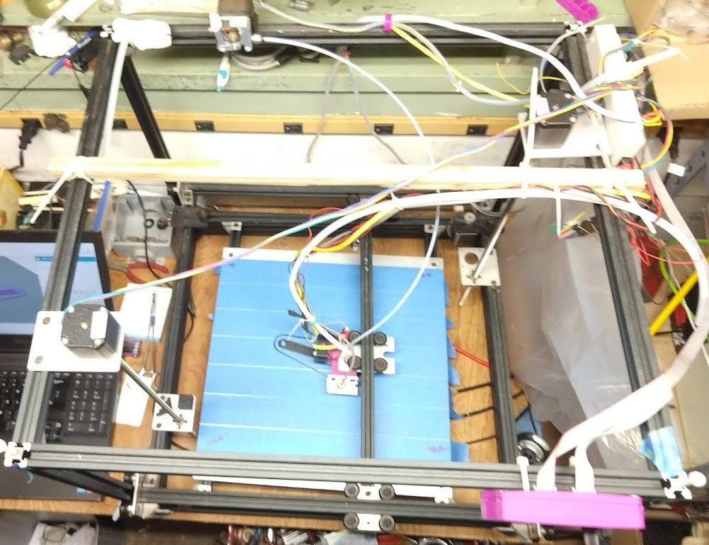
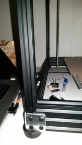
The design was actually very straightforward. It’s a big, cartesian XYZ machine constructed of V-Slot Linear Rail, with a stationary bed, and moveable gantries that carry the hotend in X, Y and Z directions. If you gave a class of college engineering students access to https://openbuildspartstore.com, and an afternoon to design a 3D printer, you’d probably get several designs that looked a lot like Cobblebot, even if none of the students had never seen a Cobblebot.
The bed heats up to 80ºC within one minute, and is always to temperature before the hotend. I don’t have my RAMPS controlling the bed, I just set the temp on the Keenovo control unit.
Lately I’m using a 0.5mm nozzle, which is great for big projects. I usually buy nozzles in assortments from Amazon.
My print bed rests on coil springs which fit into the v-slot underneath, and has 4 low profile screws which engage t-nuts in the rails, such that the screws push the bed onto the springs and provide a level adjustment. I typically keep my 15” square bed within 0.2mm of Z-variation corner-to-corner, with the bed level compensation turned off. If I tell Cobblebot to probe the bed and it measures more variation, I adjust screws.
The original Cobblebot design had the Z lead screw nut tabs sharing with the X drive axis. I split that up by buying separate tabs for the X drive at openbuildspartstore.com. When the Z and X axes shared tabs, one had to compromise between centering the Z axis, which moved the X belt into the build plate and limited Y travel, or maximizing the build volume and uncentering Z. Once you separate X and Z, the Z tabs can be set at opposite corners, which greatly improves Z repeatability and reduces binding and sag.
I would say that a majority of my time has been spent devising and applying a bed-leveling scheme. I mucked about with Mesh Bed Leveling in Marlin around version 1.0.2, got my inductive probe and UBL going around Marlin 1.1.5, and just updated to 1.1.9, in which UBL works very well, and is well-exposed in the LCD menus. The combination of the milled aluminum bed, the inductive probe, and UBL really made this printer viable.
Keeping Your Head In The Right Place
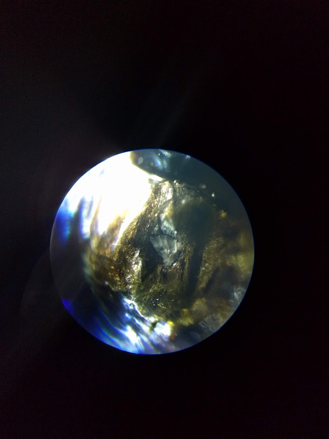
I had a learning experience last year around how head crashes, especially dragging the nozzle across the bed, affect nozzle shape. One goes through various exercises trying to get extrusion right, to get first layer contact right, and etc, but I hadn’t really thought much about nozzle damage until I decided to look at my old nozzle under a microscope.
Old 0.4mm crashed nozzle
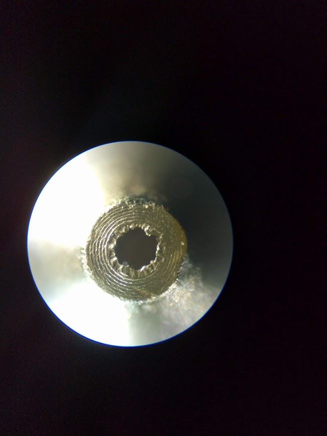
New 0.4mm nozzle
The gist is: if you do a nozzle-bed-drag, change the nozzle. Note that there is significant casting cruft around the new (cheap) nozzle, and one could seek to drill it, or something, but I speculate that trying to do anything with sub-millimeter drill bits is not part of a happy lifestyle, so I’ll live with the cruft. The crashed nozzle, on the other hand is probably pretty far from 0.4mm in terms of filament volumetrics, but also appears to want to spew sideways, rather than down. I suggest getting at least a simple microscope, for so many reasons, including this one.
Future Directions
I’ve kind of got my eye on the Zesty Nimble v2 a remote-direct drive extruder. It puts the drive in the tube, instead of the filament. Another interesting DD is the Bondtech. Either would probably necessitate changing the hotend, so I’m procrastinating, because such projects tend to get prioritized behind “real life” during which time my 3D printer is non-functional.
Another interesting wrinkle is laser cutting, which is well-documented around the web and on YouTube. Since the Cobblebot has an empty second extruder position, I think I could put a laser on there for cutting, without disconnecting the FDM hotend. I would want to make an enclosure before I start firing lasers, so that would also be a big project, but looks like it could be done within a couple hundred US$.
Printing The Bahtinov Mask
In order to avoid making a post that turns up in searches for “Bahtinov mask” and not providing what the searcher probably seeks —
With UBL and bed heat, it was not difficult to print this 10-layer mask. It took about 2 hours. It was a great test of 1st layer precision, which was pretty good, there were places where it was pretty thin, but no place where it was loose. It’s not a particularly good anti-model warping test, since there are no stresses from cooling upper layers.
The result was a bit delicate to get dislodged from the bed, but with my trusty scraper and some positive attitude, it came off undistorted. I let the bed cool to touch-able before I pried it up, but I didn’t let it return to room temp.
There are several b-masks on Thingiverse, including an OpenSCAD model that’s adjustable. The others are fixed, and either printable in two parts, or the wrong size. The OpenSCAD one doesn’t produce a manifold model. I ran the output through several fixers, looked at cleanup in Blender (which allows you to select all non-manifold vertices), but it was going to be a long slog.
In the end, I took an SVG file produced by the Bahtinov generator at:
Imported it into Blender, converted it to a mesh, and extruded it upwards 3 mm to make a solid shape. Due to weather, we have yet to test the mask on a star, but this will probably be remedied soon. I think that my aforementioned interest in laser cutting will probably produce a simpler, faster way…
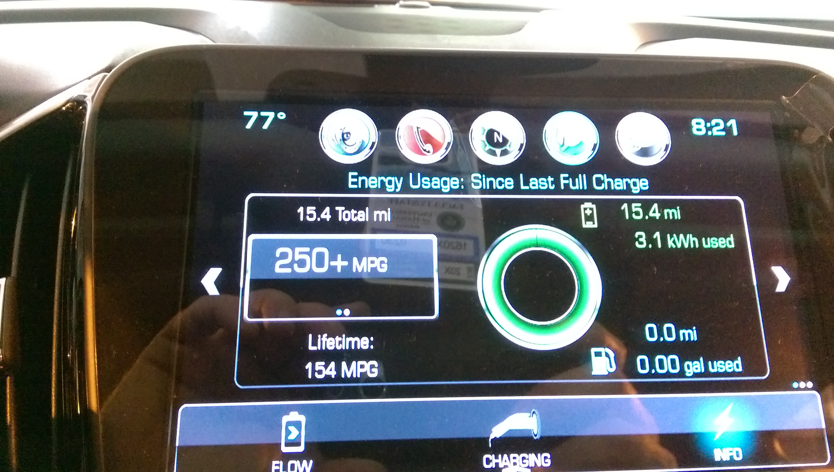
After driving 15.4 miles, the battery range is only 3 miles short of a full charge.
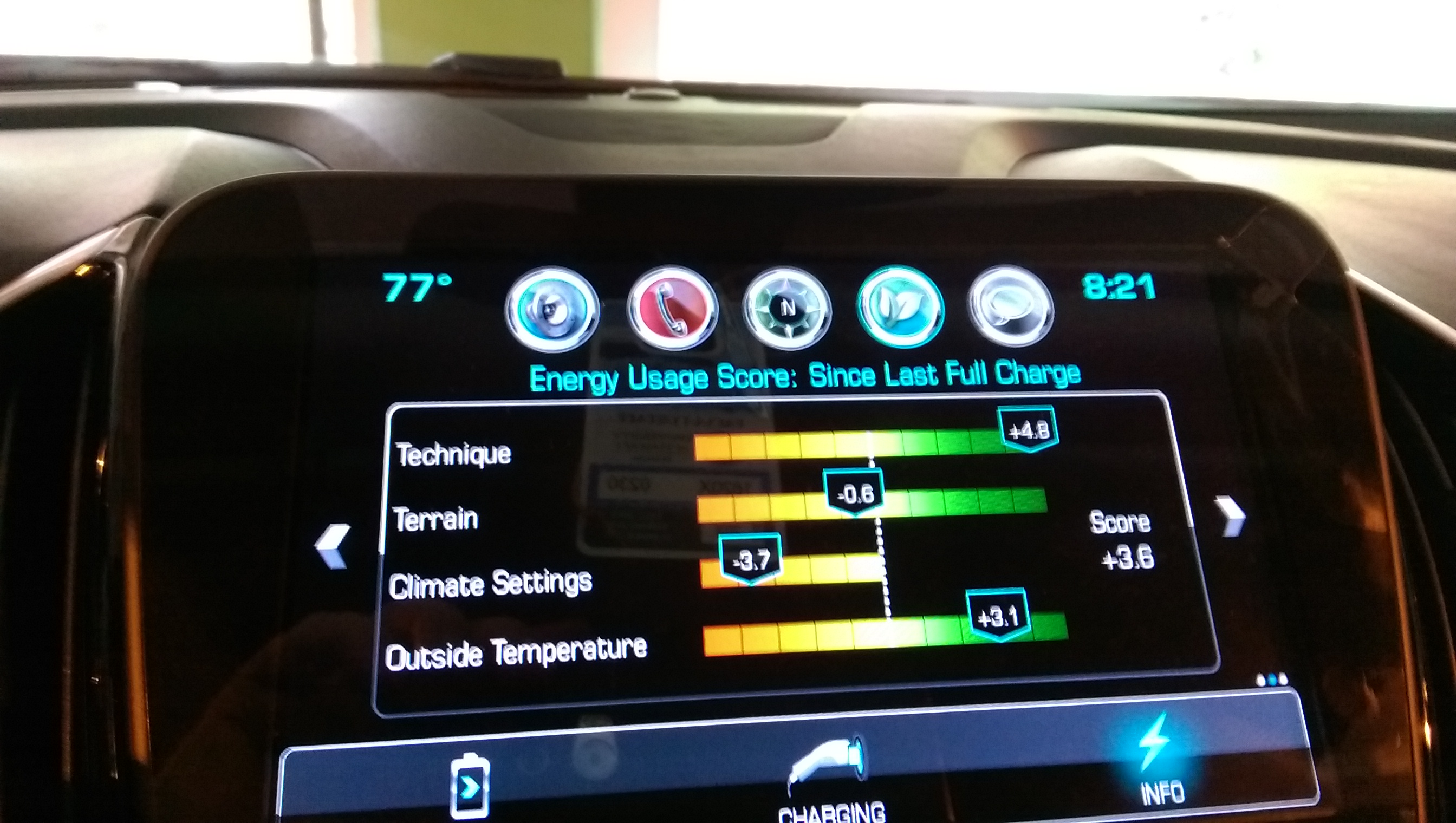
Today was the 4th day driving my 2017 Volt over a mountain range to get to work. I’ve realized something. Although people seem to consider electrics and hybrids “wimpy” or something, and one sees a certain number of conspicuous Priuses (“Priae?”) and Leafs (“Leaves?”) driving meticulously up the steep side of the Likelike Highway, it isn’t in general because they’re underpowered. It’s because they’re instrumented. Driving any of the electrics or hybrids I’ve been inside, one is face to face with the cost of one’s driving habits. When the dealer gave me Volt last week, someone had turned the climate controls all the way to the coldest setting. It took me a while to correct this, and my climate score is still only recovering.
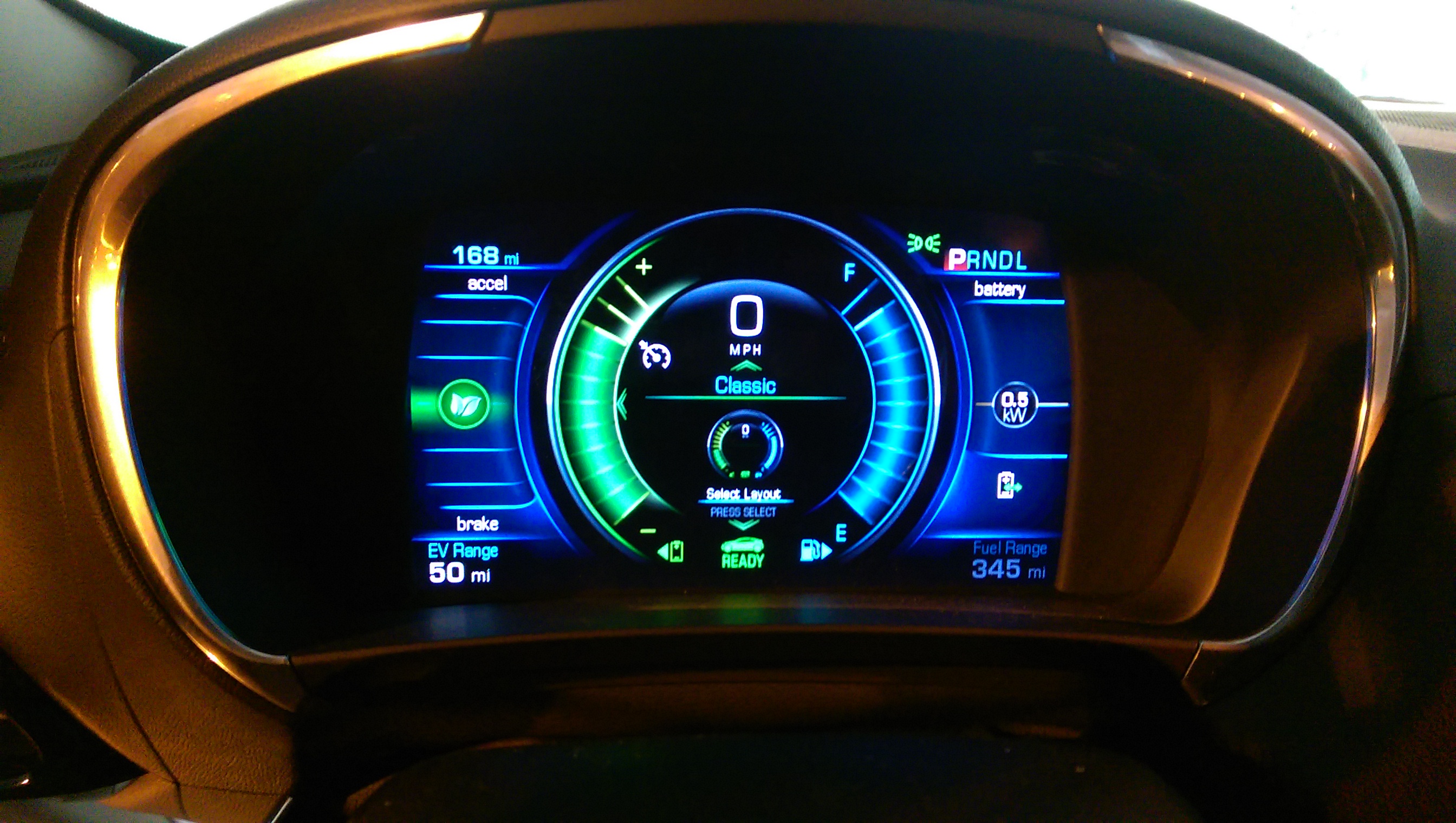
But today’s big kudo to self is for making judicious use of cruise control on the uphill side and regen-on-demand on the downhill side, to finish my 15.4 mile commute with 50 miles electric range showing on the panel. When I crested the hill, the remaining electric miles was 39, but it got back to 50 by the time I reached the parking garage.
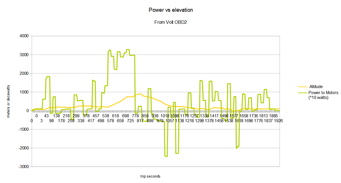
Of course, what it means in real numbers remains to be seen, but it shows the game that’s afoot. Today was also the first day I collected ODB2 info on the Volt, it’s interesting to see the KW used at different points along my route.
A funny thing about the exciting adventure of ordering a car — I actually had enough time to lose interest. We sat down with Billy at JN Chevrolet and did the order — or rather claimed one of their orders — on April 8th, and the car was delivered on May 28. So during that 50 days, I had time to sort of back-burner the whole Volt thing. Mind you, I had not been idle. I oversaw the installation of a new 120 V GFCI electrical outlet, on its own circuit, I began taking regular meter readings from the electric company’s meter, and I thought an awful lot about electric cost versus gas cost.
Why Buy An Electric Car?
Because, first and foremost, it has the potential to save money on operational costs. In Hawaii, the comparison of electrical versus gasoline used to drive to work is going to be a close thing. In the US mainland, it’s a bigger win, but in Hawaii, it’s looking like electric wins the cost picture “by a nose”, more data on that going forward. But with electric, you have the potential to reduce fuel costs to zero, with solar. Granted, that investment would be hard to justify on cost basis alone, but it’s not an option with an ICE-only platform.
Also because carbon output. I always roll my eyes when I see the “Zero Emissions” label on Nissan Leaf, since, unless they’ve got a 2 KW solar installation at home, it’s simply not so. Still, consider that your power company will generate less carbon emissions than your ICE engine to produce the same kWh of energy, and for every electric car, emissions improvements by the power company mean less emissions per mile driven. Also consider that when petroleum prices rise, your gas price rises more with price-per-barrel than your electric kWh price does, probably. So electric car is more rising-cost-of-petroleum friendly.
Also — and if I were honest, this might really be reason #1 – it’s a F**KING ELECTRIC CAR, dude. How cool is that?
[It seems that it is necessary to clarify that Chevy Volt operates primarily as an electric vehicle. There are many who would argue that Chevy has mis-categorized it, or lied about how it works, but the fact is that when the battery is within 9 kWh of a full charge, it will not use any gas. Calling it a “plug in hybrid” is probably valid, saying that Chevy misrepresents it for some nefarious purpose is barking at the moon. I stand by “electric car” as a description for Chevy Volt. ]
Why Buy Chevy Volt?
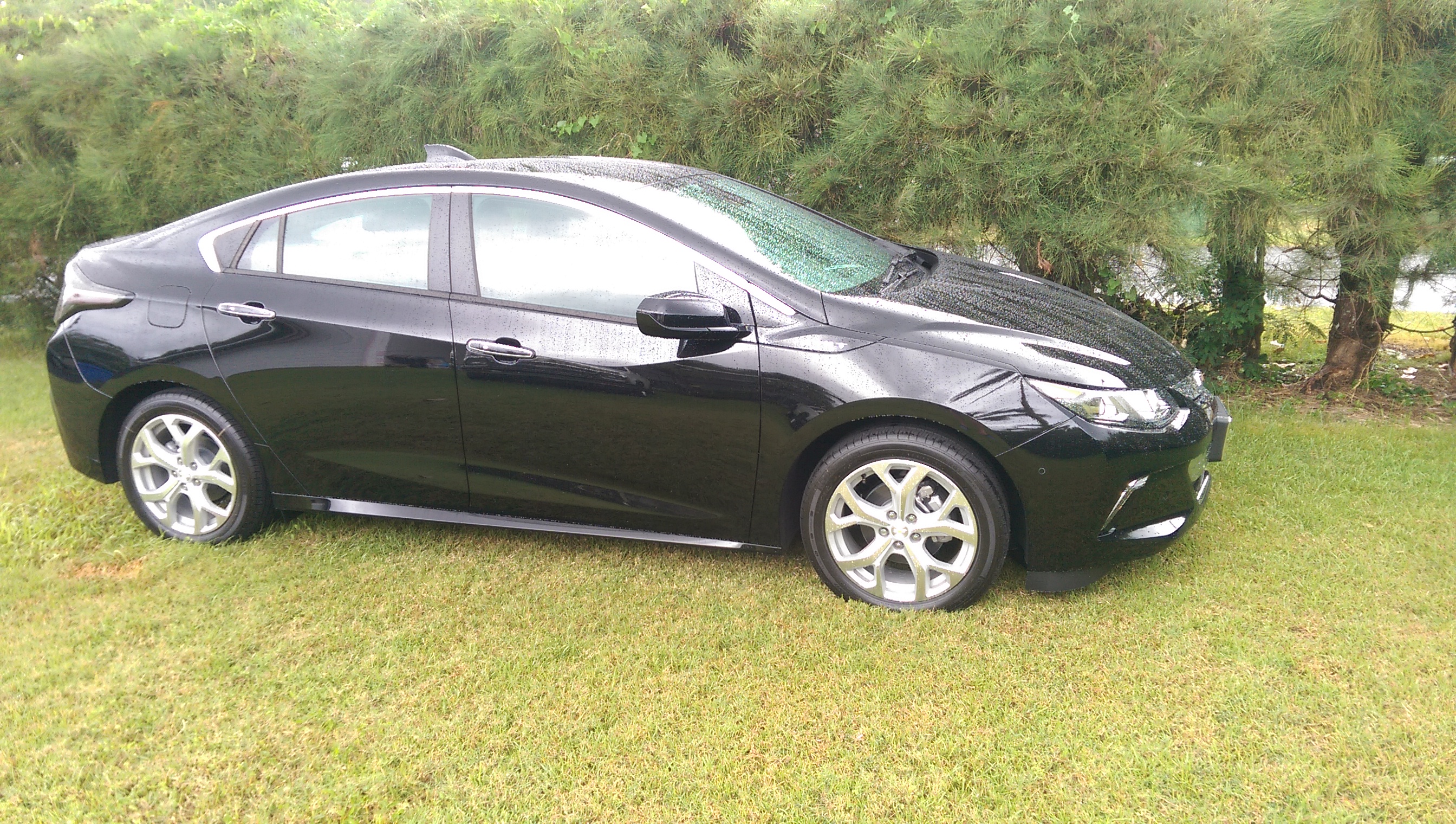
I settled on Volt initially because it’s logistically elegant. When the dealer handed me the key, the battery charge was at 0%. I got in, and drove over a mountain range to home, with plenty of oomph over the hill to stay on the left and keep up with the passing crowd. I got, according to the summary provided by Volt itself, 33 MPG with the on-board gas-burning power plant providing power. Meaning that 2017 Chevy Volt a peppy, efficient, comfortable car, even without battery power. Can’t do that with a Nissan Leaf. Also, I can charge it each day in about 7 hours, and use no gas to commute to work, saving money in the process. Can’t do that with a Toyota Prius (Toyota discontinued their plug-in hybrid temporarily, it seems, otherwise they could compete at this).
Two other things you can do with a Volt that you can’t do with a Toyota Prius are:
– get a $7500 tax credit from the U.S. Government.
– park at county and State facilities for free.
And since Volt is selling briskly, alongside Leaf and etc, the end of incentives may be approaching faster than previously predicted.
Also, it’s an awesome-nice car. I mean nice in a meaningful way, not in the ways that people seem to rationalize worthless expense. It’s comfortable, and I like the look of it. It does suffer from a slight dose of the Conspicuous Conservation Syndrome** but mostly it looks like a 2017 Chevy. I have to look for clues to tell it apart from a 2016 Cruze, or Malibu. That makes me happy.
Value Of Time-Of-Use Electrical Metering
I spent some time looking into whether HECO’s TOU metering rates were worth the trouble. The gist is this – you pay:
– 5.5 cents more per kWh during peak times (M-F, 5PM to 9 PM)
– 2.5 cents more per kWh during mid-peak times (M-F, 7AM to 5 PM, S-S 7AM-9PM)
– 6 cents less during off-peak (7 days, 9 PM to 7AM)
Which means that you get a discount during the normal EV charging time, but you need a strategy for doing laundry or other big-energy activities at night, or pay more for it. If you can line-dry clothes, solar heat your water, then TOU may work in your favor, but it’s a bit of a wash (unintended pun) either way. For us, the decision seems to come down to paying $5 or $10 dollars per month to avoid the annoyance of avoiding peak-rate electrical use (we have solar hot water). Plus, that 8 hours of cheap energy per night might not be enough to feed the car, so the non-TOU option allows more freedom to do a catch-up charge on the weekend.
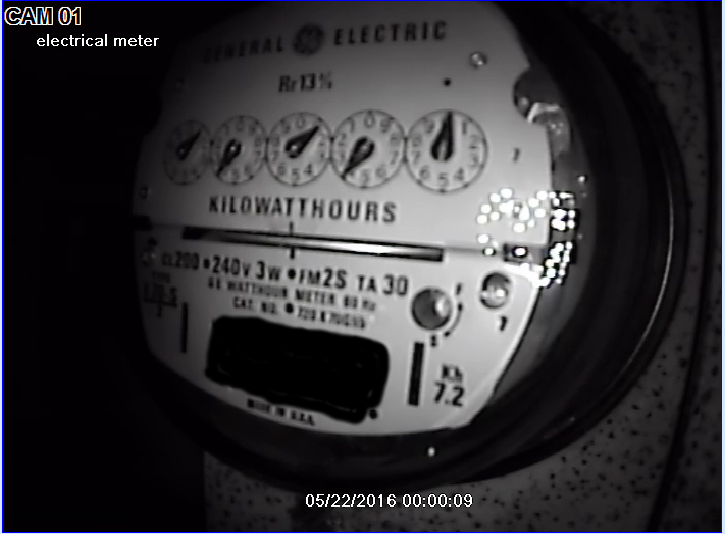
How did I evaluate the benefits of TOU? I did buy parts for the Open Energy Monitor a month ago, but life being what it is, I haven’t got it set up yet. As a stop-gap I took an extra security camera and connected it up to the home security DVR, to record the electric company’s meter, 24 hours a day. This has proven to be a really handy thing.
I made a spreadsheet with readings from the meter at 7 AM, 5 PM, and 9 PM over the course of a month. Considering the cost differences and introducing a car charge estimate of 8.5 kWh on commute days and 5 kWh on weekends, TOU would save about $0.28 per day, or about $8.53 a month.
You could increase the TOU advantage with some behavioral changes, but the level of cost and the desirability of the changes, and the ROI pay-off to offset the new meter installation gives me pause.
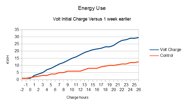
The Initial Charge
As I said above, the car was delivered with the battery at 0% charge, so it was necessary to do a full charge at home. I got it started at about 4:35 PM on Friday (sorry HECO, but no TOU), and charged with an 8 amp limit for about 16 hours, paused for a while and began the charge again with 12 amp limit for another 2 hours.
Comparing my readings from Friday/Saturday one week earlier, the full charge appears to have used about 17 kWh.
As of this writing, it remains to be seen how much the commute, with its trip over the Ko’ola’u Mountains, will cost me, but in mileage terms alone, it would be about 9.6 kWh per day, based on Chevy-provided figures, but when has OEM new car mileage ever played out in real life? At a gas price of $2.50 and a kWh price of $0.29, the number of kWh to beat is about 8.6 kWh per commute*. It might actually be cheaper to commute in the Volt with gas. But not by much. There are other factors to consider.
After the drive home from the dealer, Volt produced the sobering statistic that 32% of my energy had been spent on climate control. It may be that driving with the windows open would be a big energy saver. Also, there’s the matter of the regen-on-demand paddle. This control, which is under your left-hand fingertips when you have your hands on the steering wheel, causes Volt to convert momentum into battery charge when pressed, effectively causing braking in the process. On the downhill side of the mountains, one can choose between driving faster or saving money. Hmmmm.
If you can believe it, after getting through the 18 hour charge, I still didn’t find a reason to go drive the new electric car in the day and a half since I got it home. I will try to do better in the future.
Hopefully, I will get more-better numbers on the economy of Volt in the coming weeks. Stay tuned.
*competing with previous car 2013 Toyota Corolla, which gets about 30 MPG on my 30-mile round-trip commute, according to many odometer-versus-gas-pump calculations.
** to enjoy Freakonomics Radio podcast in your electric car, see:
Judging from the recent increase in new faces around the Google+ Cobblebot Community, there are numerous kits reaching backers, and many of them undertaking the build. Some have come up against the firmware config and compile/upload as confusing. I had done Arduino stuff before, and although I’m new to 3D printing, I have worked as a prototyper engineer in the past, designing and building and making electro-mechanical things work, so I may not realize what it’s like to start from scratch. Still, I think that this build is do-able for most people with the inclination. There have been claims made, to the effect that the parts are simply too terrible to work, or that the design is so flawed that it’s hopeless. Both of these are clearly not true, no more than claims by the company that the parts they supply are adequate.
My printer is built with as few mods as possible. The things for which I “rolled my own” are:
I replaced the stack-o-bearings idler pulleys with these.
I contrived my own spring-loaded bed-leveling system.
I mounted endstops, which the official instructions glossed over.
I added a fan to the hot-end heat sink, with tie wraps.
I added spiral cable binding, tie-wraps, and a salvaged electronics enclosure
I added a few screws and t-nuts, which I bought extra from OBPS.
Other than that, I used what was supplied by CobbleBot, and I’m making progress in getting print quality to a useful level.
My CobbleBot has the following characteristics:
Z-motors are at the top. This was pretty easy to do, and I did it because there tends to be binding in the lead screws when the motor coupler gets close to the nut. If this binding happens at bed level, then you’re screwed. If this binding happens at the top of the travel, your build height is limited, at some point. With my bed mounted above the tops of the base rails, I’m currently getting 270 mm of free Z travel.
Z endstop is at the bed level. For a long time, I had it at the top, but one spends an awful lot of time slewing to bed level after a homing procedure. I had thought of using things like (Marlin) mesh bed leveling or (Marlin/Repetier FW) numeric auto-leveling, but the setups for those things all assume that Z home is at the bottom. Also, Slic3r inserts this “raise nozzle to 5mm/lower nozzle” thing which is great with bottom-homing, but less so when home is at the top and the “raise nozzle to 5mm” is actually a lower-nozzle-265 mm at breakneck speed.
I also put 10 mm M5 screws into t-nuts under each Z-gantry where the gantries should be at Z-home, so that there is a hard-reference for Z-gantry-levelness. NOTE that when you drop t-nuts into the vertical rails, you should put a pencil or something in the groove at to top of the base rail so that the nut doesn’t simply disappear into the base rail at the bottom.
X and Y endstops are at MAX.
This just sort of turned out this way. I chose to reverse the direction of Y, to make coordinate zero be in the front. For X I forget. But the endstop placement for X and Y seems to be a lot more arbitrary than it is for Z.
(This is a work in progress. It may already contain useful stuff, so I’m publishing it. Expect further — ask questions in the Google+ Community).
Raw notes follow:
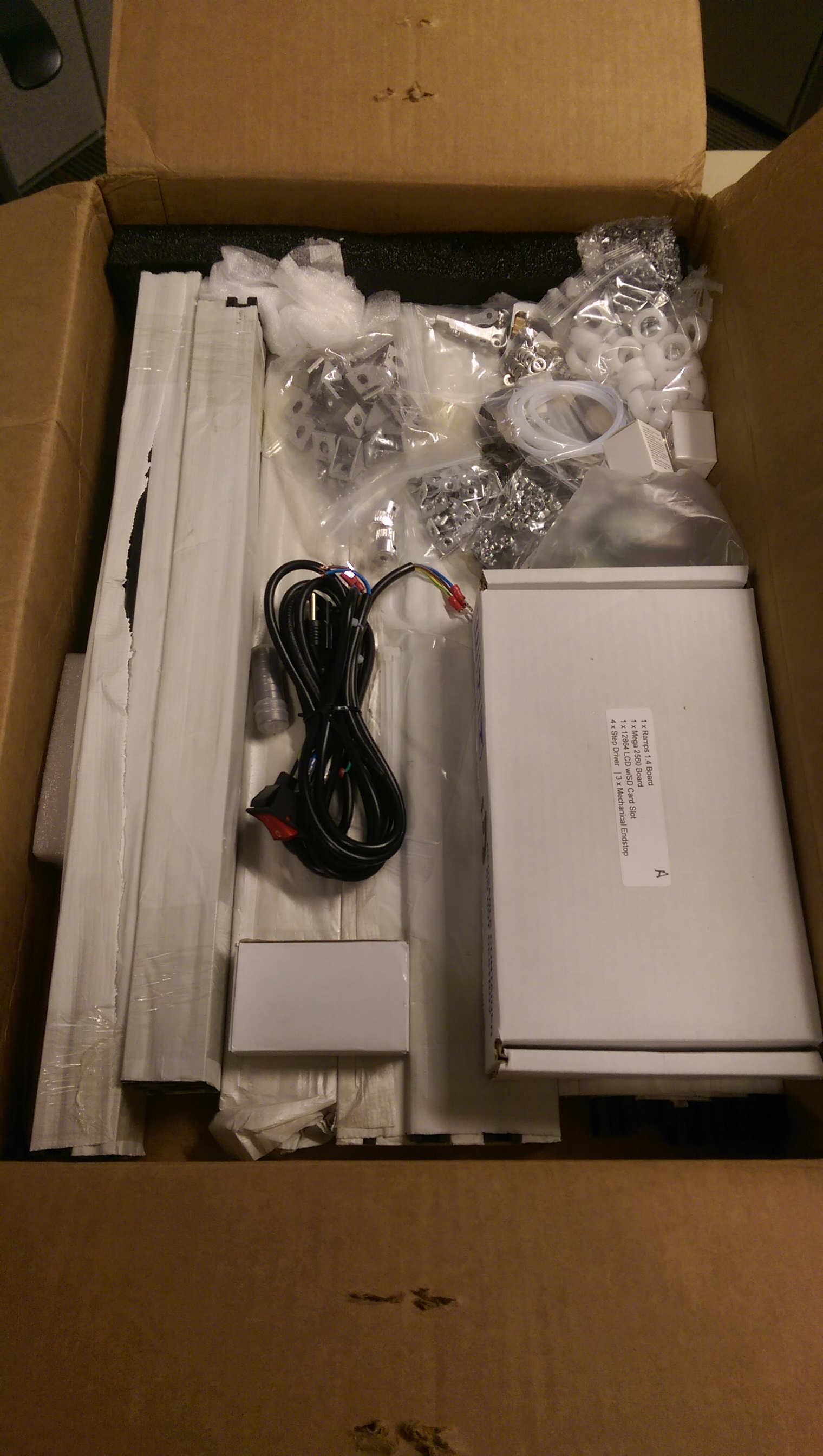
I received the second box of 2 on June 6, 2015. I got:
DRV4988’s (red versus DRV8825’s which are purple),
white “acetal” wheels. Mine were pretty reasonable, not full of some of
the defects I’ve seen on others’. Still, to fit the bearings into the
wheel took a lot of force.
metal plates, even though I don’t think I selected them as an
upgrade
one of two push-fits for the bowden PTFE tube was 5mm (4mm is required)
The build instructions are available at Cobblebot.com. Log in, search
for “Cobblebot Basic Hardware Assembly Guide” (or whatever version you
have). You need to purchase the instructions for $0.00.
==========================================
Tools:
allen wrenches:
At least a set of metrics, with 1.5 mm, 2 mm, 3mm.
I found that I wanted both the loose L-shaped set,
as well as an insertable bit to put in a screwdriver-style
handle. A motor driver might be good — not a drill, but a
gearmotor screwdriver. Drills are too fast and too powerful.
Open-end wrenches:
3 mm
10 mm
Wire cutters (side-cutters/dyke-cutters)
Needle nose pliers (or maybe big tweezers).
===========================================
Little heat sinks.
I bought little heat sinks for my stepper drivers —
Which appear in my pictures. You may wish to get some of these also.
They come with peel and stick adhesive on the back to stick them on the
chips.
I bought a batch of DRV8825, too —
which come with heat sinks, but no adhesive to attach them. Luckily, I
have enough of the other heat sinks to supply them all.
===========================================
Screw specs;
M5, 0.8 thread pitch — most of the frame assembly
M3, 0.5 (?) thread pitch — lead screw nut mounting screws, extruder
bracket to M3 T-nut, and any screw that screws into a motor body.
M4, 0.7 – extruder spring screw (I had to replace the nut, got one at local HW store)
The M3 screws for mounting the extruder bracket on the frame would be better off as hex-head (as in turnable with a crescent wrench, rather than an allen wrench), so you could tighten them from the side.
I found M5 x 0.8 screws at Lowes in the little drawers, and M4 x 0.7
screws/nuts/washers (part of the extruder at a local Hawaii hardware store called City Mill.
==========================================
For the lead screws, I and at least one other builder have found white lithium grease to work well. Not too messy, once you’re done touching the lead screws, so maybe lubricate after the build.
==========================================
When building gantries, I found that a little white lithium grease in
the eccentric spacer holes was a good thing.
When you put the gantries together, initially rotate the eccentrics with a 10mm wrench, so that the wheels are as far apart as possible. You can rotate them to go tighter on the rails later.
My rule of thumb is that I should *just* be able to rotate the wheel with my thumb and forefinger when its engaging a rail. You may find that there are places where the inside wheels are really tight, and the outside are loose, or vice versa. It’s always good during construction to have assembled things semi-tight, meaning not prone to slipping, but slip-able under a little force, so you can work things up and down, or right and left, etc and let them find their place in the world, followed by full tightening.
==========================================
If you are missing wheels: see this Google+ thread:
If you get no wheels, you need wheels.
The bearings that Cobblebot sent us do not work well with the shims that
Cobblebot sent us. The above discussion covers this.
With appropriate shims
(such as: http://openbuildspartstore.com/mini-v-wheel-precision-shim/)
the Cobblebot bearings *might* work OK, or you might get most of them
working and need a couple, or you might just want to buy 28 of these,
which include everything you need for the wheels EXCEPT the M5 x 25mm screw:
http://openbuildspartstore.com/solid-v-wheel-kit/
If you order wheels, or whatever, consider getting a bag of tee-nuts:
http://openbuildspartstore.com/tee-nuts-25-pack/
Plus, there are these — t-nuts that can be inserted into the groove
without sliding in from the end, but I thought they were too expensive…
http://openbuildspartstore.com/drop-in-tee-nuts/
The Bowden extruder pushfit deficiency:
https://plus.google.com/113777585643345712764/posts/gwboiQzGim9
Your kit should include two small brass fittings, which slip onto the
PTFE tubing that guides your filament from the filament extruder motor
to the hot end. I received one which is for 5mm tubing, which had a
black release button, with a “5” imprinted on the button. The ones that
are correct for 4mm PTFE tubing tend to have blue release buttons, and
have a “4” imprinted on the button. Cobblebot acknowledged the
deficiency in an update, but says that they plan to ship replacements
after all printers are shipped. You should open a ticket if you got the
wrong pushfit connector.
I obtained a replacement from Amazon:
“PC4-M6 Pneumatic Straight Fitting for 4mm OD tubing M6 6mm Reprap 3D
Printer etc”
I built my CB with the first draft instructions, but the second were
tl;dr for me, but note:
You need to insert the following t-nuts before assembling the related rails:
In the base 20 mm x 60 mm, long sides, place 4 t-nuts on the inside of
each of two longer rails. Typically these are in the top groove, but you
can put them lower, to increase build height. These will support the
90-degree brackets to hold the bed supports.
In the base 20 mm x 60 mm, short sides, place 2 t-nuts on the top edge
of each of the two shorter rails. These will connect the Z drive motor
plates to the frame. (This assumes that you are going to mount the Z
motors at the bottom. I moved mine to the top. But if you bought more
t-nuts, you don’t care. :^) )
On the shorter, lower rails that make up the Z gantry square, put 2
t-nuts into the top edge groove on each of two rails.
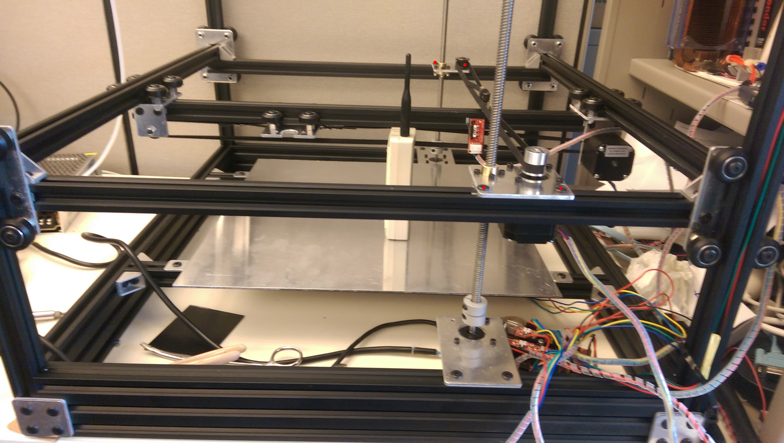
Illustrations — red dots at locations of relevant t-nuts, assuming some
x-ray vision.
(CDMA time standard radio not included with Cobblebot)
The Blog re-sized these pictures so that they kind of suck. I will work on that.
ALSO: you will need to insert 3mm t-nuts (of which you may have precious
few) for endstops, and for the extruder mounting.
=========================================================
Cable Organization
You need to pick a spot where your Arduino/RAMPS are going to reside.
This is probably best-off in the back, to keep the cables out of your
face, and it works well to mount the assembly on the top rail. This will
help in routing cables to the hot end, which needs 3 pairs — the heater
power, the thermistor sensor, and the heatsink fan power. You may also
consider a fan to cool the print, and to that end, if you route a cable
for the hotend fan, use cable with at least two pairs in it.
Getting the Z gantry assembly (with X and Y already installed into it)
to fit onto the vertical rails.
I had to build it with the cross-rail screws semi loose, so I could fit
it onto the 4 uprights and get the spacing right, and then tighten one
(kit 1A) or both (kit 1B) to fix the width.
(need pictures to clarify WTF I’m talking about).
====================================================
As far as the SD card reader and LCD are concerned, I’ve done nothing
with them, yet. Early on, I plugged it in and the Arduino wouldn’t boot,
so I abandoned them for the time being. You don’t need them to print,
and even if you want them, you’re probably better off using a host
software like Pronterface or Repetier Host to get your CB working.
=====================================================
Assembling the extruder:
Do what Mike Kopack says in this video (it’s not completely obvious):
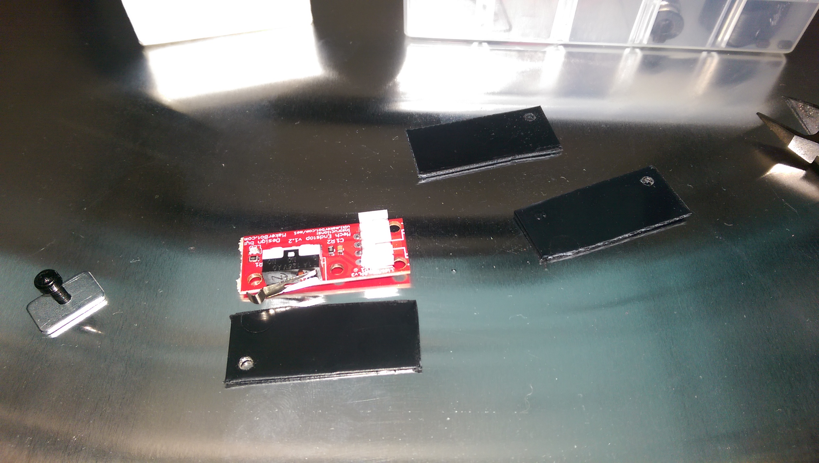
The Official Instructions are notably lacking and somewhat obtuse
regarding endstops. They suggest putting electrical tape on the solder
side, and then putting endstops at “the minimum” on each axis.
Electrical tape is an *unspeakably* *shitty* idea, don’t do that.
I made plastic plates by cutting up dividers from those annoying little plastic drawer parts cabinets, with scissors. (Really tired of people telling me to “just 3D print it” when I didn’t have my 3D printer built yet). Notable that there’s only one hole on the endstops where you can put a mounting screw. I may bootstrap my endstop mounts now that I can print tolerably well.
(need pictures to clarify WTF I’m talking about)
I originally set up Max endstops on all three axes, but in the end, I
moved the Z endstop to the bottom.
I have endstops that contact wheels, but I can see that over time, the
rotation of the wheel will distort the lever on the limit switch. It is
better to contact gantry plate edge or rails than it is to contact wheels.
Do this:
http://www.marlinfirmware.org/index.php/Setup
I am using Marlin 1.0.3dev (use the “Latest Development version” in the
above tutorial.)
Your should find these lines in the file “Configuration.h” and change
them per the following (assuming you have DRV4988 stepper drivers (red). If you have DRV8825 drivers (purple), the DEFAULT_AXIS_STEPS_PER_UNIT numbers will be something like double) :
#define MOTHERBOARD BOARD_RAMPS_13_EFB
#define CUSTOM_MACHINE_NAME “Cobblebot Basic”
#define EXTRUDERS 1
// Or if you have 2 extruders, you can put “2”.
// but I suggest getting one working first.
#define TEMP_SENSOR_0 5
// per http://reprap.org/wiki/Hexagon
// IF you find that some motor or other is moving the wrong direction,
// you can affect that here:
// Invert the stepper direction. Change (or reverse the motor
// connector) if an axis goes the wrong way. Below is how mine are
// YMMV
// below tells Marlin which endstop you are using and what direction an
// axis has to move to reach said endstop
// ENDSTOP SETTINGS:
// Sets direction of endstops when homing; 1=MAX, -1=MIN
// :[-1,1]
#define X_HOME_DIR -1
#define Y_HOME_DIR -1
#define Z_HOME_DIR -1
// You will have to find the following out for yourself.
// When you get so your machine can home reliably, then you can use
// host software to move to extents. If your Z motors are more toward \
// the center, you will have shorter Y, if your Z lead screws start to
// bind at 275 mm, then make this 270. My philosophy has been to get a
// working printer, even if the build volume is a little reduced, and
// and then you’ll be fighting less uncertainty and fewer variables
// in expanding.
// Travel limits after homing (units are in mm)
#define X_MIN_POS 0
#define Y_MIN_POS 0
#define Z_MIN_POS 0
#define X_MAX_POS 311
#define Y_MAX_POS 255
#define Z_MAX_POS 288
// Go gently at first, then try higher speeds later, especially in Z
// Homing isn’t really that critical speed wise — you want to
// home accurately, and then print well.
#define HOMING_FEEDRATE {50*60, 50*60, 4*60, 0} // set the homing
speeds (mm/min)
// default settings
#define DEFAULT_AXIS_STEPS_PER_UNIT {80,80,400,94.5}
#define DEFAULT_MAX_FEEDRATE {300, 300, 16, 25} // (mm/sec)
// I reduced the bejeezus out of Z. It can sound like it’s smooth, but
// miss steps, nonetheless.
=========================
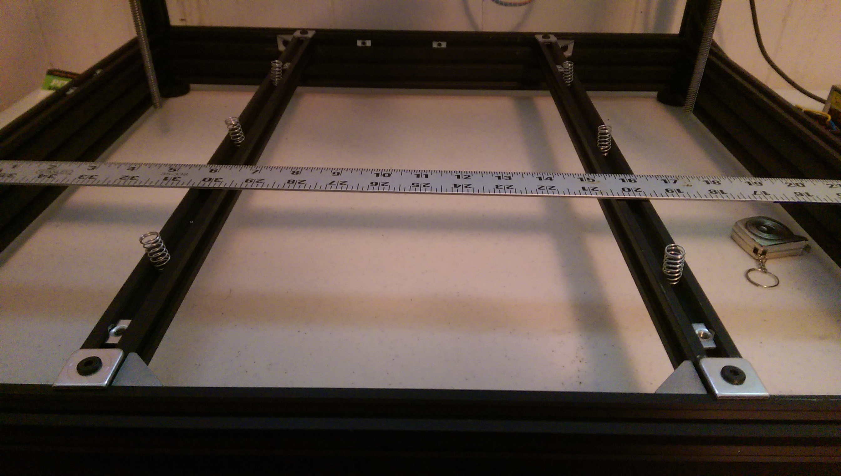
The adjustable print bed
I bought a pack of 6 springs at local hardware store, which slide into the v-slot rails that were provided as bed supports.
Also, I used the square bed mounts provided by CB to support the ends of the rails, so that they just drop in are essentially flush with the top of the base rails. I secured the ends with one 90 degree bracket per end.
I drilled (like, 6.3 mm) holes the bed so that M5x25 mm screws could engage t-nuts in the rails, and then I drilled corresponding holes in the rails so that the screws have clearance to go deeper, through the rail. I did not put the screw through the spring, but it’s important to keep the end springs next to the screws. If there is space between the screw and the spring, then tightening will warp the bed as it gets toward the bottom of the adjustment.
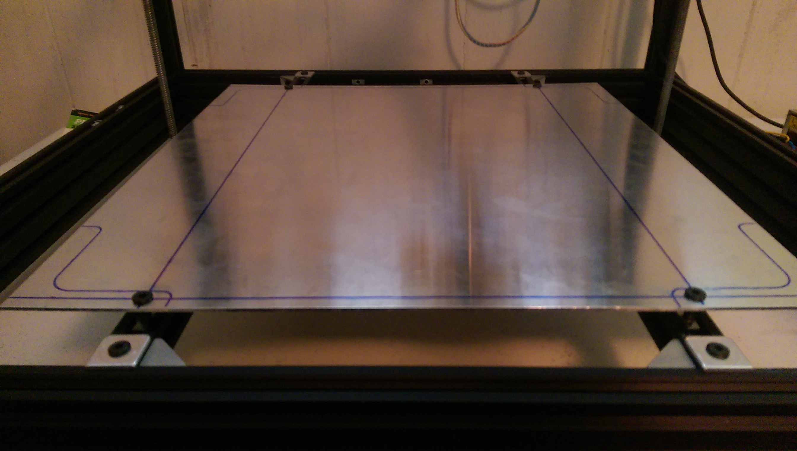
It will take a couple of rounds to get the bed adjustment to “surround” the Z-gantry error. I recommend setting the Z min endstop with the bed mostly compressed, and 2 or 3 mm of space between the bed and the hot end nozzle. Then you can rotate screws counter-clockwise until the gap between nozzle and bed just barely grips a sheet of printer paper. I have had good luck leveling with my Fleks3D plate sitting on the CB aluminum plate, secured by binder clips. Typically, I adjust for the 4 corners and then the center of my build footprint. My bed layers are mostly flat — if yours aren’t, you may have more hoops to jump through. A sheet of glass (I found some 12×12 mirror tiles that are pretty good) clipped onto your aluminum bed may average things out enough that you can calibrate to the glass and have a reasonably flat surface. So far, my observation is that if the bed is equidistant from where the Z-gantries bring the nozzle, then it doesn’t matter that the Z-gantries aren’t flat. The only complication being that the Z gantry motors can get unsynced, or the frame can be torqued so that it changes. The former seems to be more of a problem than the latter. If the motors are at the same level (measure from the base rail to the lower z-gantry connector rails at each side, and you get a frame of reference for how lopsided it is.
Since I have rails kit 1A, the obvious adjustments to flatten the Z-gantries is unavailable when the gantry cage is assembled. I’ve been tempted to either:
buy 1500 mm of vslot and make longer rails.
OR
Drill the vertical rails to make an access hole to loosen the screw at when the Z-gantries are at the bottom.
When last I printed, I had gotten the bed into a place where I couldn’t raise the bed enough to grip the paper on one corner. I plan to go back and center the bed adjustment in the middle of its range, and then see that the endstop and each of the other 3 corners is bracketed by adjustment, if possible.
Useful to remember that the adjustment screws are 5mm x 0.8 thread pitch, so when you need to move the bed up or down on millimeter, it’s about 1.25 turns. Or 0.1 mm is about one-eighth of a turn, etc.
My caliper says my printer paper is about 0.1 mm thick.
CT Angiography From Wikipedia: http://commons.wikimedia.org/wiki/File:Ct-angiography.png
Last Tuesday night, I faced the cord-cutter’s dilemma: having consumed all 6 seasons of the Sopranos from Amazon Prime, which I had been grazing upon since March, I needed something new to watch. This is the moment when cord-cutting most resembles the old channel-surfing model, where one pokes around and finds something that one had not previously encountered. It can yield new information, despite the best efforts of Netflix, Amazon, etc to make sure that what you watch today resembles what you watched yesterday.
A source of new input, not surprisingly, tends to be the “newly-added” list, which on Tuesday featured a new movie called “The Widowmaker” prominently.
From the description, it wasn’t entirely clear whether the movie was a documentary, or a fiction, but it was compelling enough. “Starring: Gillian Anderson” it said. Although I’ve never really been an X-Files fan, I tend to enjoy the projects that she chooses. Maybe it was fiction. I craved escape, and if it was a documentary, I would just back out and try something else, I thought. But that’s not how it turned out.
The Widowmaker is a documentary about the development of a medical screening methodology called coronary calcium scoring, in parallel with the invention, development of the coronary stent and the growth in its use by cardiologists. The name is based on a nickname for the anterior interventricular branch of left coronary artery, which is intended to grab your attention, rather than to describe the content, but poetic license probably bridges the gap. It’s obviously designed to lead you to a viewpoint, and much of what is said is compelling, but it has the tone of something that, although reasonably well composed, needs to be verified by other means. To that end, I submit that my take-away from The Widowmaker pretty much matches the abstract from a study I found on PubMed at the National Institutes Of Health:
[Computed tomography coronary artery calcium scoring: review of evidence base and cost-effectiveness in cardiovascular risk prediction.; Vliegenthart R, Morris PB., Department of Radiology, University of Groningen/University Medical Center Groningen, Center for Medical Imaging-North East Netherlands, The Netherlands. r.vliegenthart@umcg.nl]
The entire abstract reads (emphasis mine):
Cardiovascular risk factor-scoring algorithms may fall short in identifying asymptomatic individuals who will subsequently suffer a coronary event. It is generally thought that evaluation of the extent of the atherosclerotic plaque and total plaque burden can improve cardiovascular risk stratification. In the last decade, there has been an increasing interest in coronary calcium scoring by computed tomography. By determining the calcium score, an estimate of the total amount of coronary plaque is obtained. Numerous studies have shown that the calcium score predicts coronary heart disease. Recently, the calcium score was shown to improve risk stratification beyond cardiovascular risk factors, especially in those individuals deemed to be at intermediate risk. So far, only limited data exist on the cost-effectiveness of coronary calcium scoring in asymptomatic populations.
According to Ms. Anderson (who is, in fact, channeling Patrick Forbes, the writer/director of The Widowmaker), and also according to Vliegenthar, et al (the authors of the above-referenced study), there are individuals for whom the checking of risk-factors, like weight, age, cholesterol, etc. will not predict their coming heart attack. The movie goes on to say that EKG, or even a cardiac stress test (which includes an EKG) does not serve to detect impending “coronary events” in some patients, many of whom show no risk factors anyway, so they may not have had such tests.
It’s probable that your doctor works with you and chooses tests, treatment, and other actions based on what he assesses as your risk, using profile types that take into account such factors as your age, weight, smoking, high blood pressure, family history, etc. If you don’t match a certain risk profile, then the chance that you will suffer the relevant problems is considered acceptably small.
But there’s a problem with that.
Low-probability of risk isn’t zero probability of risk, and therefore, there are some number of people who will have the problem, even when their risk profile indicates that their risk is acceptable. These people have names, addresses, families and are people, who — no delicate way to put this — might be You. Somewhere, a guy who’s sporting the realized risk, that is, one of the acceptable-number-of-guys who is going to have the unlikely heart attack, based on his risk profile, probably has a doctor who’s doing the same risk assessments for him.
Consider the Cardio Vascular Disease Risk Calculator at the National Institutes of Health web site. Below the calculator is information about what “good” numbers would be for each of the calculator’s fields. I entered all “good” numbers, and my age, 53. According to the calculator there would be a 3% chance that a person with “good” numbers would have a heart attack within 10 years. In other words, out of each 100 53 year old, non-smoking men who have “good” numbers for blood pressure and cholesterol, 3 will have heart attacks within the next 10 years. Using 2010 census data to estimate that there are roughly 2 million 53 year-old males in the US right now, that 3% is equivalent to about 60,000 heart attacks, or an average of 16 unexpected heart attacks per day, over the next 10 years, just among 53 year-old males. (edit: I need to adjust this, since not 100% of 53 year-old males have good numbers)
The Widowmaker tends to paint the opposition to routine coronary calcium scoring as cardiac-stent-obsessed robber barons, who are promoting the application of expensive stents into patients for whom the stents have no benefit. The most mainstream-media-apparent expression of stent value in improving patient outcomes, the COURAGE Trial* , suggests that medical treatment, such as statin drug therapy, is as effective as stents in treating coronary heart disease. Unfortunately, statins have their own detractors.
The movie also asserts that hospitals have prevented bankruptcy by the revenue that stenting provides. In the movie, as well as on the wide internet, there is a certain amount of that pooh-poohing and brushing-aside by doctors who seem to want to play down coronary CT scans for any purpose, often without completing their argument, leaving us to simply accept, “because a doctor says so”.
I think that doing what your doctor tells you to do is probably a good rule to follow, but if you assume that doctors speak candidly, without restraints from management, litigation risk, and frustration at the endless barrage of patients who misapprehended something they read on WebMD, you would be doing so, perhaps, at your peril.
If profit-motivated health care service providers are in it for the money, why are the insurance providers reluctant to reduce the need for a $30,000 stent by paying for a $200 coronary scan? I admit that I am missing pieces in that inquiry, but in the movie it’s stated that they recognize that their customers don’t stay with an insurance company for more than a few years, and that screening would only benefit their competitors.
Society, that construct of which we are participants, creators, and victims, should seek to promote public health, and better probabilities for more of us, but it never seeks to monitor and manage the health and welfare of each of its persons. Even democracy, for all the marketing it has enjoyed in popular culture, will never be an inclusive model. The police protect economic stability, rather than people. Broadband Internet initiatives serve people who happen to be near statistically-important parts of statistically-important cities. Free shipping promotions on e-commerce sites are great unless you live in Hawaii or Alaska. If your needs are not the needs of a majority, they aren’t a priority. The knack of living long and well, especially for those of us who are counted in the little slivers of the pie-charts of acceptableness, is to manage it ourselves.
Perhaps the salient point in all of this, the point that can negate the value of this inquiry, is in the question asked by one of the detractors in the movie (I paraphrase) “So you find out that you have significant coronary plaque. Then what?” Some of us will have a hereditary predisposition that has decided our fates for us. Some of us will be unable to bear the thought of life without potato chips. Some of us will get stents, and/or statins. Some of us will adopt a healthy lifestyle, and some of us will drop dead. But none of us, without surgical procedures, will encounter a determination of whether what we did helped or hurt us, cardiovascularly. It’s primarily speculation.
Still, I’m willing to accept that our culture —
which paints itself as epicurean, but is in fact simply hedonistic,
whose participants eat for convenience, rather than for nutrition, and
who have come to equate “freedom” with the absence of accountability
may not do its best to promote personal health.
Mind you, it’s probably among the most survivable cultures in history. The post-smallpox, post-cholera, post-polio, world we enjoy is, by 1910 standards, astonishingly low-risk. But that’s due to the effects of applied public health, not individual health. One can’t really predict and prevent heart attacks, but one can manage weight, blood pressure, and refrain from using tobacco, among other things.
Watching The Widowmaker, even though I see the need to question the veracity of something that’s obviously a “hearts and minds” pitch, has had an immediate effect on my daily habits. My FitBit One is currently preparing for shipment from Amazon. Even without it, the Android FitBit App tracks my activity, logs my calories, and graphs my weight (entered manually), and I have to admit that I want FitBit, inexplicably, to be proud of me. The occurrence of boredom-snacking in my diet has ceased. My waistline has been pushing the limits of my wardrobe this last year or more, and just the consideration of my own risk factors has given me a long-sought handle on the problem.
There are few, if any, coronary calcium score detractors who go so far as to say “don’t ever get one under any circumstances”. The argument is more aptly paraphrased as “it has no value if you’re not in a 50% or higher risk group”. Meaning that even if you haven’t been told that you need one, there really isn’t anyone who’d object if you wanted to pay for one yourself.
Question is: who would offer such things in a world where the scan is largely not used? Or put differently, in a profit-motive-based health care industry, who has the proit-motive to offer cardiac CT scanning? Well, stand-alone radiology service providers, of course.
Although I don’t presume to have invented Recreational Radiology as a pastime, I do see the allure. It appeals to the techno-fascinated nerd boy in me, as well as my lust-for measurement engineering side. I called Ko’olau Radiology on Thursday, after a day of hesitation. I expected to be told that there would be an appointment available in 3 or 4 weeks, but the lady said “any time starting tomorrow morning is fine, cost is $418”. After that declaration, I found the view from the precipice atop my warm, cozy denial bracing. A mere 19 hours later, I was inside the GE Lightspeed CT scanner, with my arms over my head, and EKG pads on my chest. CT scanners are to be found in pretty much any modern radiology provider, but the cardiac program probably requires that the scanner be equipped with a program to image the heart at rest between beats, by taking the EKG as input. I speculate that adding that capability to a CT scanner isn’t cheap, since nothing is in the world of high medical tech. (Reference the cost of CT scanner maintenance training from GE.)
Their largest radiology-wear was barely big enough. Take the hint.
The results will arrive in the mail. A benefit of Recreational Radiology is that I get all the results, without omission, and no doctor can keep them from me. I chose, at no extra cost, to share them with my GP, and with my aviation medical examiner (who is a cardiologist), primarily because I want them to be included in both medical records, and secondly because no matter what either doctor thinks of it, I will have exposed him to it. I may benefit by my own test, others may benefit from my doctors’ exposure.
The pending results have the potential to be the most valuable medical results I had ever received, the one that delivers The News. Or it could lack any worthwhile guidance. The crux is, perhaps, “conclusive results are bad, inconclusive results are less bad.”
I felt that it was important to blog this during the blessed interval between having the test and getting the results. When you think about it, the best course of action really doesn’t depend on my coronary calcium score. I am 53 years old, about 50 pounds overweight, with treated/controlled high blood pressure. I have serious doubts that most doctors would have discouraged any cardiac screening test, based on my risk profile.
Of course, Denial is waiting, just beyond the firelight, to creep back in. Hopefully the re-calibration-of-denial is lasting.
The substrate of personal health is outlook. One can’t act to live longer when one feels as though one is already beyond help, but as I said, this is a speculative undertaking. Your lot in life is largely what you declare it to be. The whole “count your blessings/stop and smell the roses” thing, as trite as it seems, could be the key to long life. You count yourself lucky, or you count yourself out.
Epilogue
Despite my readiness to wax Pagliacci-esque over the news when my calcium score came, my score turns out to be zero. This is, of course, encouraging/disappointing, and it doesn’t mean I will live longer, but perhaps makes several other modern-day causes of death budge into the foreground of my personal health inquiry. Still — outlook is the way to go, as well as perhaps a few celebratory potato chips.
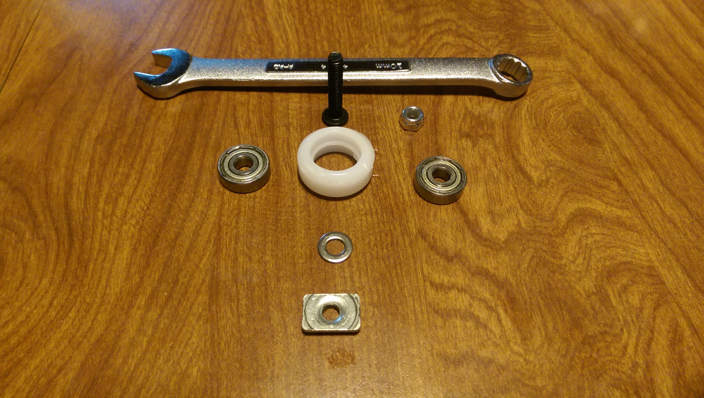
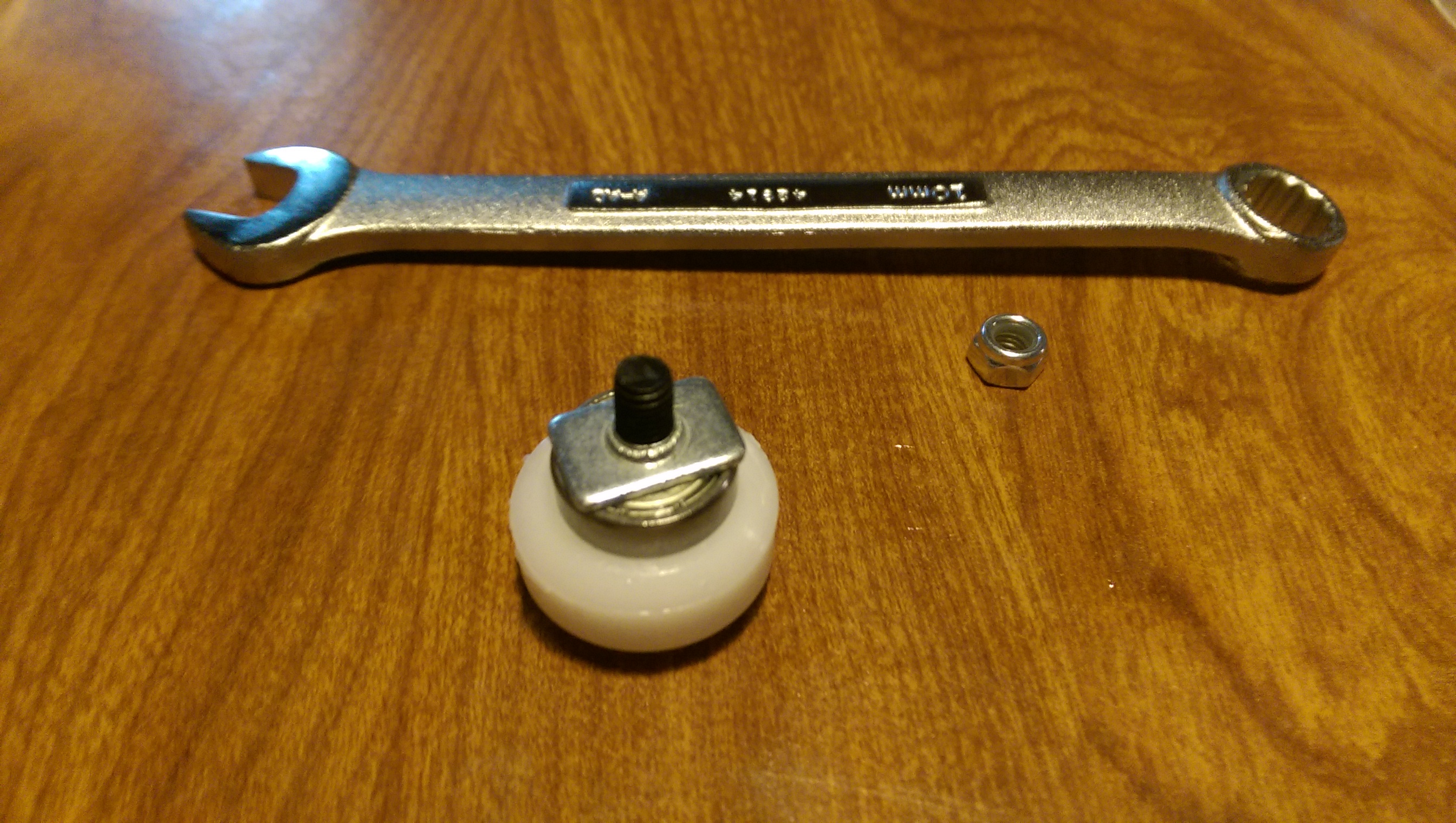
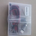
The first procedure in the Cobblebot build is about putting the wheels together. I watched Mike Kopack’s video where he used pliers, to good effect, and then in the month since, have wondered a few times whether one couldn’t just tighten the nut and push the bearings in that way. I came up with an alternate way to get the bearings in, using a 5 mm t-nut. The bearings have a sticky grease/rust inhibitor on them, so you may want to get a piece of paper or cardboard to work on. Probably best not to rub your eyes or eat finger food while you’re working with the bearings.
Pic above shows everything you need, minus the hex 3mm hex wrench, which I forgot to put in the pic.
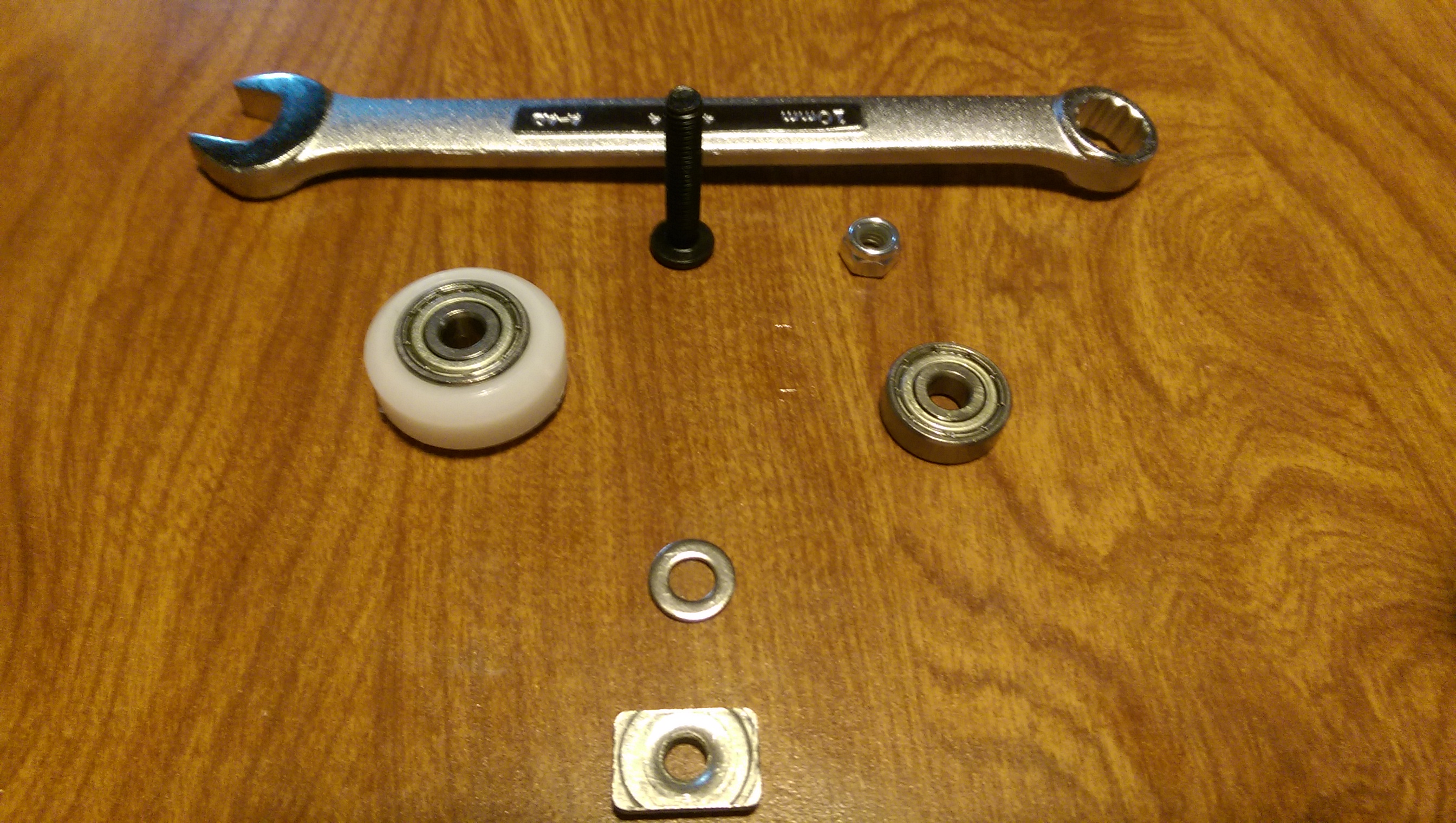
I was able to get one of the two bearings in by just pushing it in with my fingers.
Put the wheel with the one bearing onto the 5mm screw.
Don’t forget the washer between the bearings.
Place the second bearing on the screw.
Spin the t-nut onto the screw, flat side down, until it is snug against the top of the bearing.
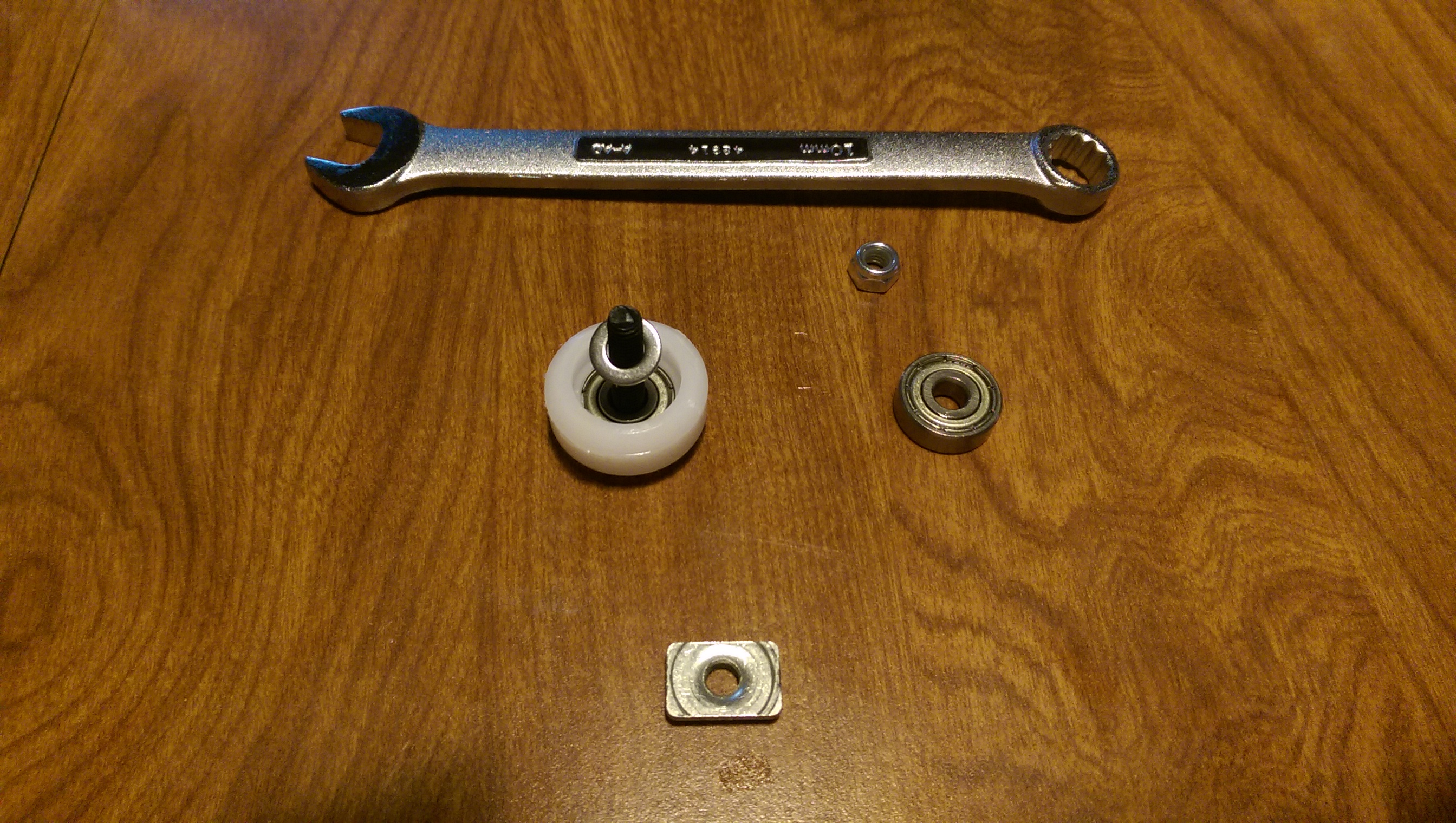
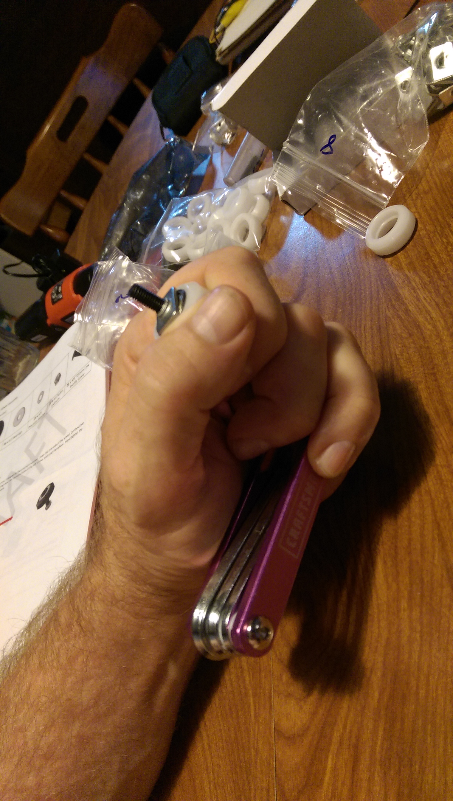
Seat the head of the screw onto the end of a hex wrench.
Use a 10 mm open-end wrench (or pliers, or a Crescent wrench) to turn the t-nut, which will push the bearing into the wheel.
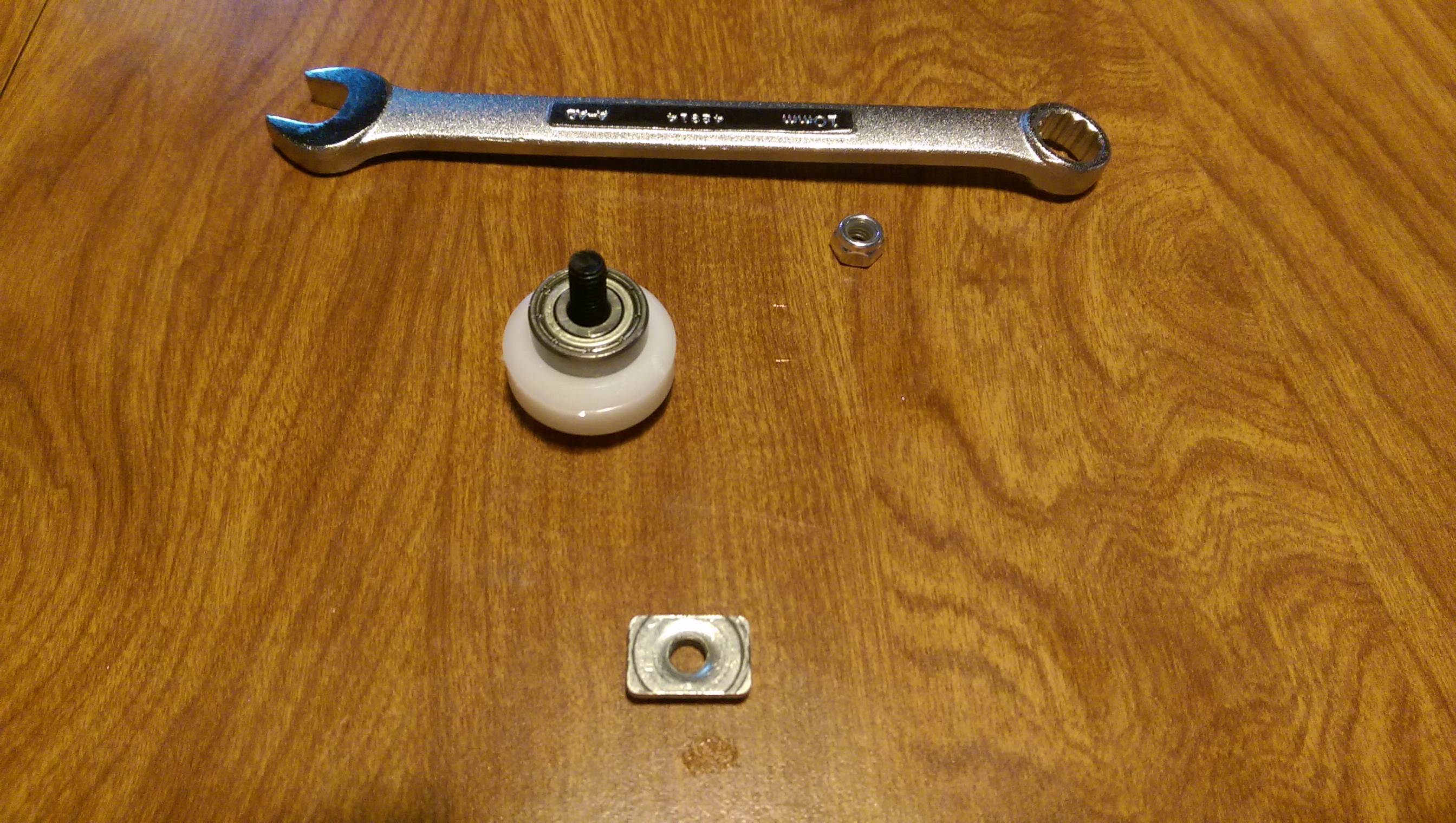
An example grip to hold the whole configuration while you’re tightening the t-nut. Also, the tightened t-nut and the seated bearing.
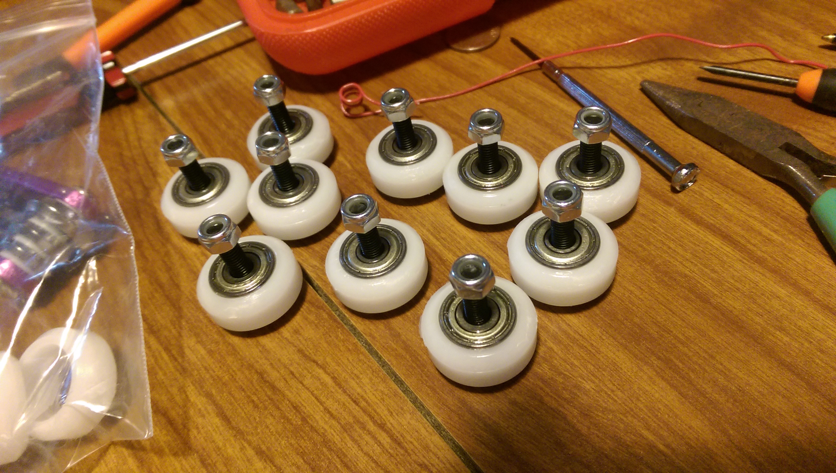
Remove the t-nut (use it again for the others). Finger tighten the lock nut onto the screw, place with the others.
Repeat 27 more times.
I had some trouble getting the pictured hex wrench into the heads on 3 or 4 screws. The hole in the head which accepts the hex wrench was really tight. When I tried a different hex driver, a cast-formed bit for my electric driver, it was much easier to get into the disagreeable screws.
(I think that the folding hex key set as pictured is made by stamping into a die, and the wire that they put in the die needs to have just enough material to fill the die, without being too much, which is a hard balance to strike, especially for screws like these M5 guys, which have really close tolerences on the drive hole, which is good. The casting process used on the driver bits (I have this set) puts the right material into a mold, so it’s a less finicky process.
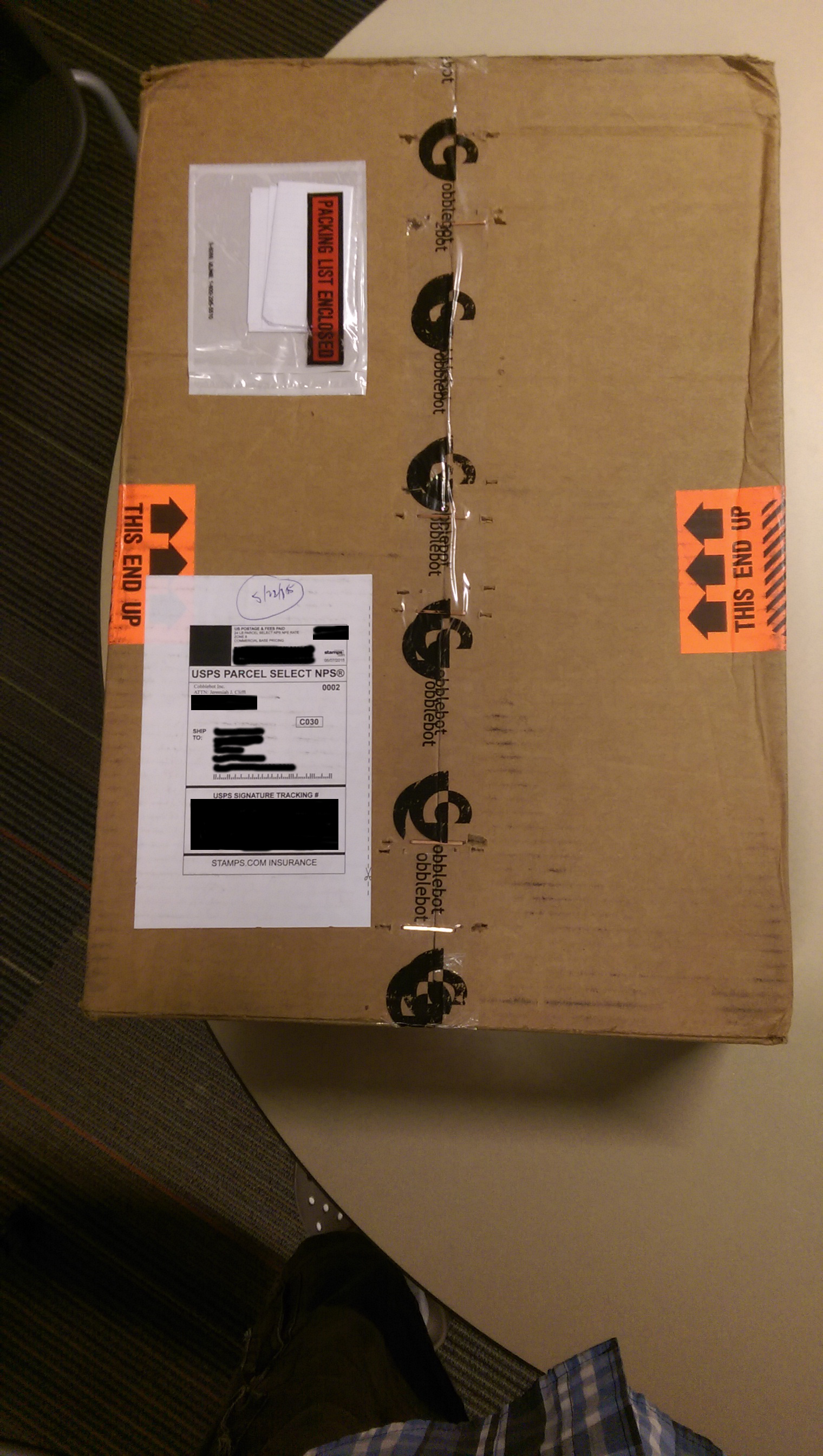
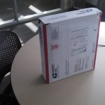
The remainder of Cobblebot came on Friday, right before the 3-day weekend, even though USPS tracking predicted Tuesday after Memorial Day. I did a thorough inventory, comparing to the parts list in the instructions, and found that it is all there, AFAIK, with a few extras not listed in the currently-released build instructions.
On Saturday, I spent time with the electronics, not to build them, but to test them and make a few videos about how they work together. Unfortunately, I’ll need to upload those on Tuesday. I started to upload them from out here at the Lake Cabin, but the Internet connection becomes unusable for other things, and it would take about 12 hours, anyways.
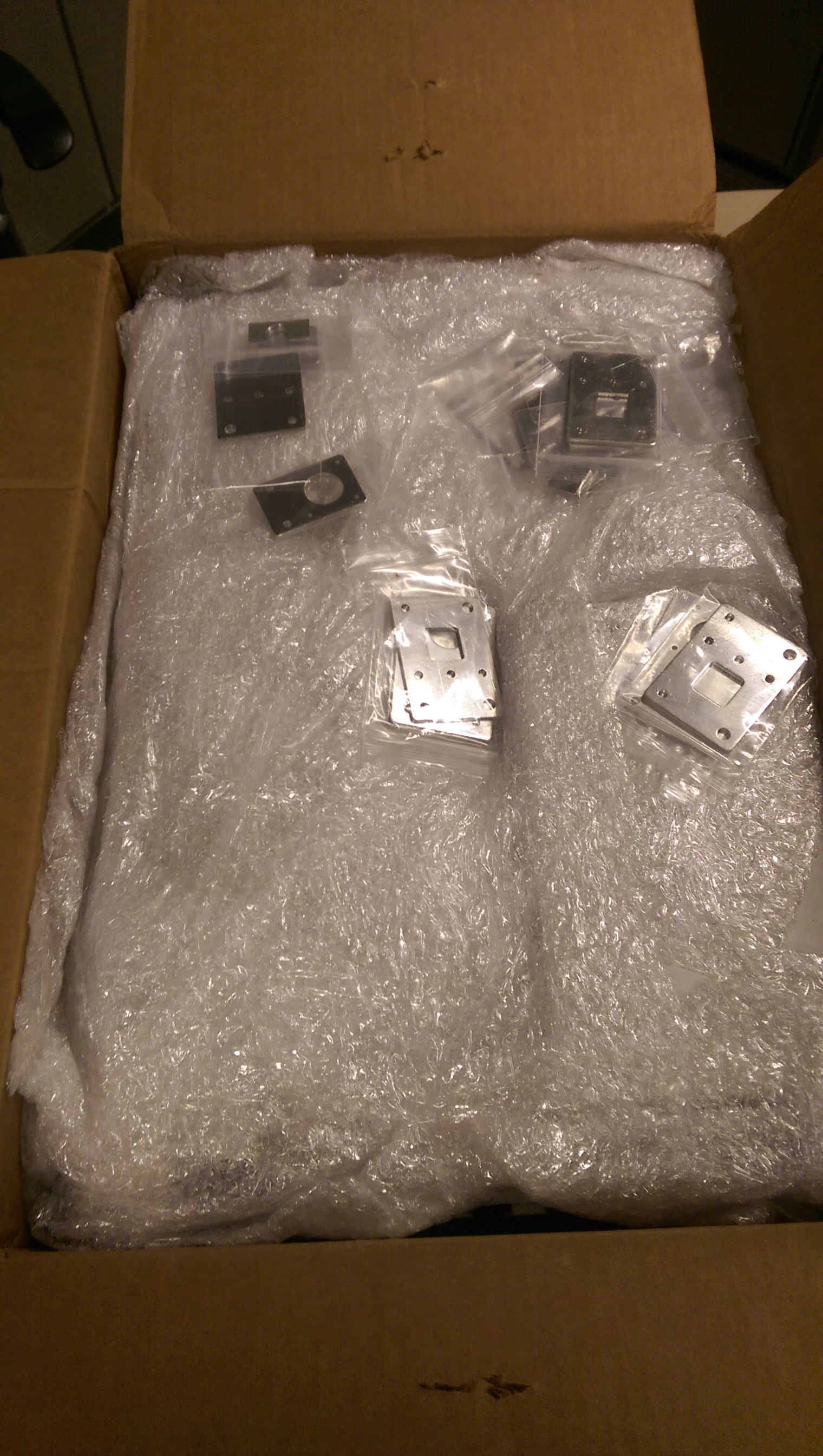
Some unboxing pictures:
I did a complete count, there were a few extra nuts and what-not, but nothing missing…
Amongst the lore of our family is a story, one of several, of my Uncle Smiley, who stated: “When we were living in Florida, we bought 100 feet of black garden hose, and spread it across the roof of the house. We never spent another penny heating water.”
When I got a look at our electric bill for August – $193 – I realized that there was probably good reason to seek out a new way to make hot water. So I followed the vision of the abundant garden hose.
How might one connect The Hose to one’s tank heater? I wondered. This inquiry led me to the Heliatos bottom feed connector (PDF), which led to an appreciation of the EZ system.
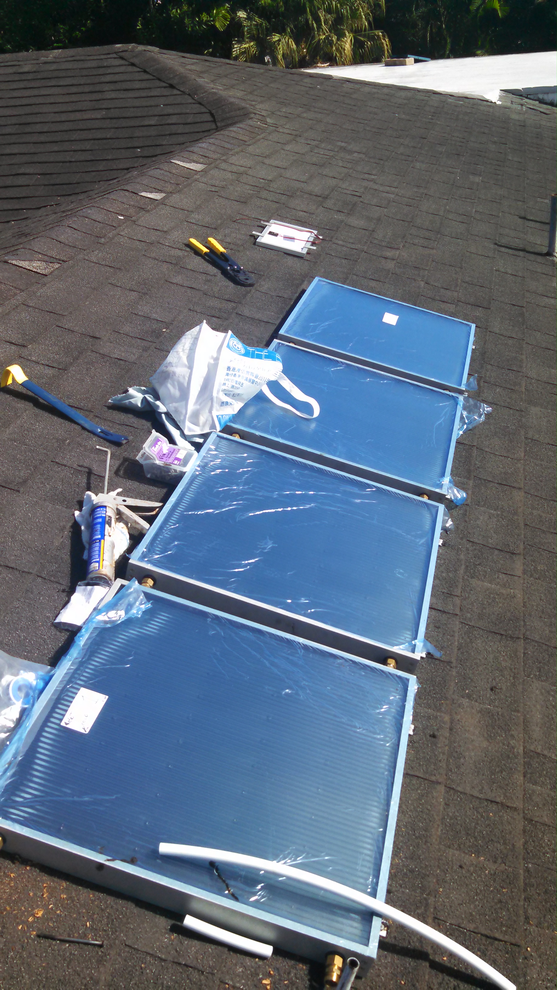
For about $1100, including the tools and accoutrements to be PEX-capable, I got it up there on the roof. The roof offers southwest and southeast faces, I chose southwest, because our hot water needs tend to occur in the evening, and because it puts the panels over the garage, where a leak would be considerably less worrisome.
I actually received the 4 panel EZ system in September, but then I had two out-of-town trips coming, so doing new plumbing seemed unwise. I hate getting a call about something gone awry at home when I’m away, and when I do, it’s better when I am not the direct cause. An additional advantage to waiting was that my wife was leaving town for two weeks, November/December, and the prospect of having a no-hot-water interval at home during the install was easier to bear with her somewhere else.
I got the bottom feed connector installed the evening of Thanksgiving Day (after enjoying a lovely buffet at the Hale Koa). I had sort-of-dreaded this step. Existing plumbing doesn’t always follow your plans, especially in the humid salt air of Hawaii. Luckily, this water heater is only about 6 years old, and everything’s still pretty shiny. I had let the tank cool for a couple of days, which gets showers down to about skin temperature, to avoid flushing too much money down the drain, before draining the tank. In retrospect, I should have planned to do a proper clean and flush, by removing the bottom heating element and spraying the mud in the bottom of the bottom of the tank, but there’s no reason I can’t still do that.
The installation of the BFC was, in fact a little dicey due to the fact that the only part of the internal nipple assembly visible outside the insulation was the threads on the union, so I had to devise a way of turning the thing to acceptable tightness without hurting the threads. I put several wraps of teflon tape on the boiler end and turned it in, first with a piece of leather between the pipe wrench and the threads, and later just turning gingerly with the wrench teeth on the threads themselves. Luckily the boiler threads were pretty clean and easy to turn into, and also the type of union used in the BFC has a rubber gasket that acts as the water barrier, so nicking the threads on the union isn’t quite the problem it would be on regular tapered pipe threads. Somehow, the BFC fits inside the water heater closet door, without modifications, something I spent time assessing and worrying about.
The interconnection of panels, per instructions, took probably a couple of hours, and I did the better part of half of the work downstairs, by finishing the left side of each connection, leaving only the right side to complete on the roof. At one point, my skim of the instructions left me with the impression that the connectors on the last end of the last panel should be connected together, but it turns out that they need to be capped. If I had made that mistake, the panels would have been curiously ineffective, and it probably would have been frustrating to diagnose and fix. The design of the panels relies on the water flowing bottom-to-top through the panels, which is a slightly more resistant flow path than a pipe, so adding a pipe on the end would effectively bypass the panels. I think that ideally things should flow bottom-to-top, since the heat-diffusion-based flow of the water in the panel would assist, and I think that if you reversed the pipes, the detrimental effects might not be noticeable.
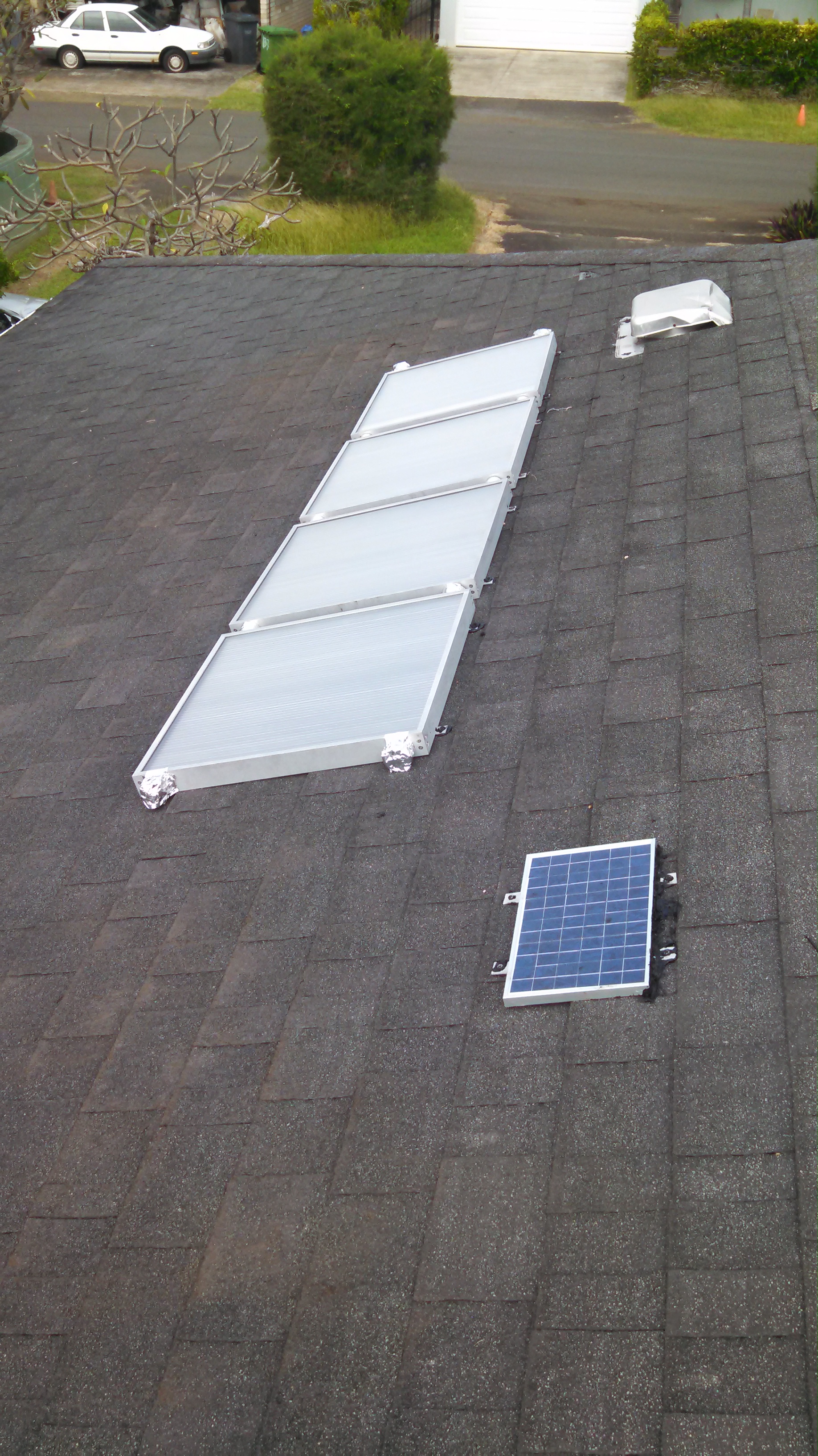
I thought and read a lot about panel mounting, and I finally ended up just squirting a pillow of roofing sealant into each mounting bracket and then deck-screwing through the sealant, shingle, and roof boards. I was blessed with two days of hard rain immediately following the install, which produced no drips.
One flurry of squirreliness occurred around the installation of the PV panel. They give you the panel, some wire nuts for the pump motor end, and 25 feet of wire. The connection for the panel end, however is neither well thought out, nor easy. There are two solder points to connect the wire, and two screws holding the little metal tabs to the panel body. The connection point is covered by a little plastic slide cover, which allows enough room for, well — nothing. One could try to simply use the screws with crimp-lugs, but the screws are inclined to thread in once, and any removal and re-install makes a not-very-connected connection against the metal of the tabs. I ended up soldering the connectors, and then smooshing a ball of Coax-Seal into the connection box, to exclude water, which seems to have worked. I also ran a bead of roofing sealant along the top of the panel to direct water around the panel when it rains.
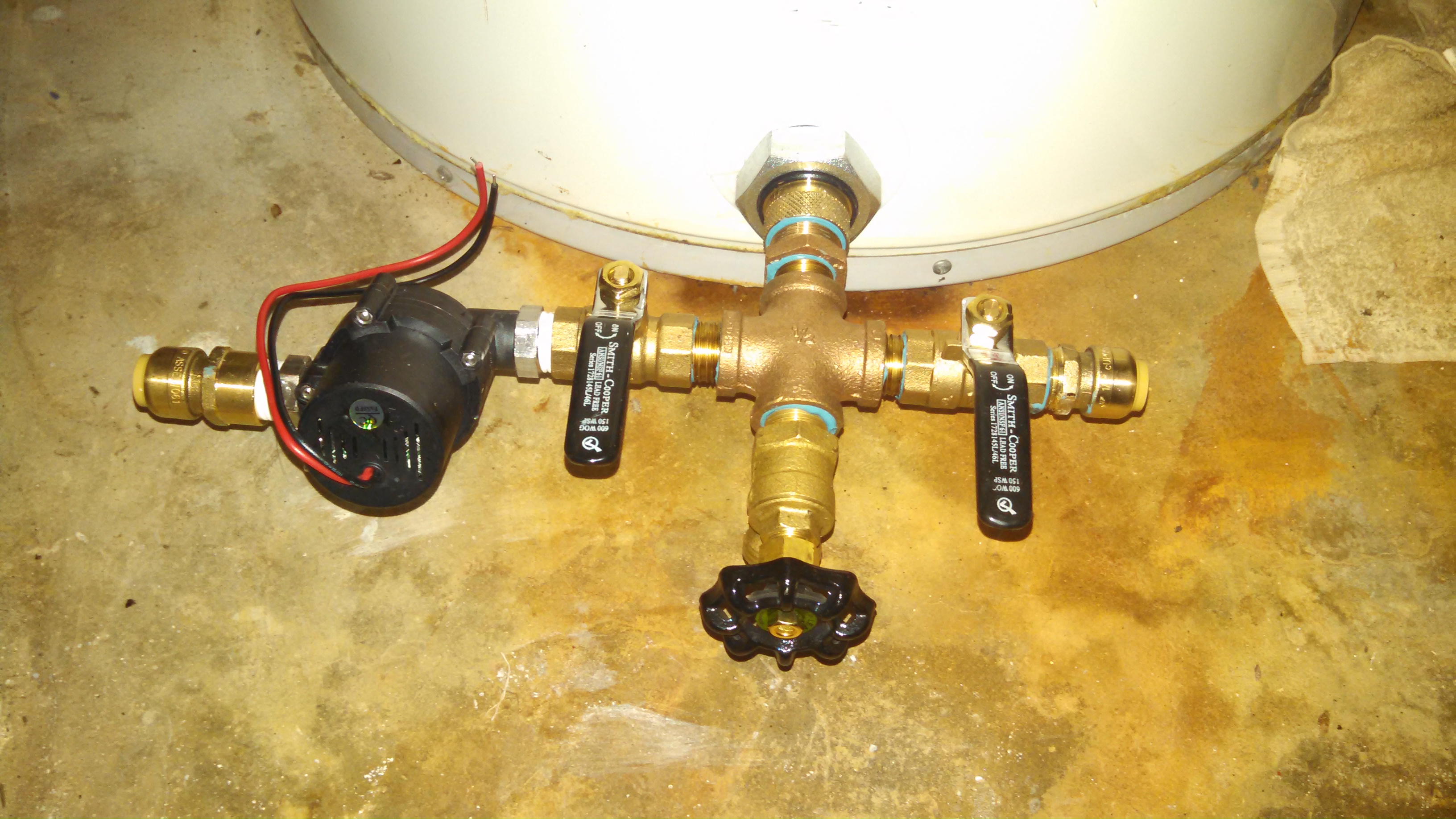
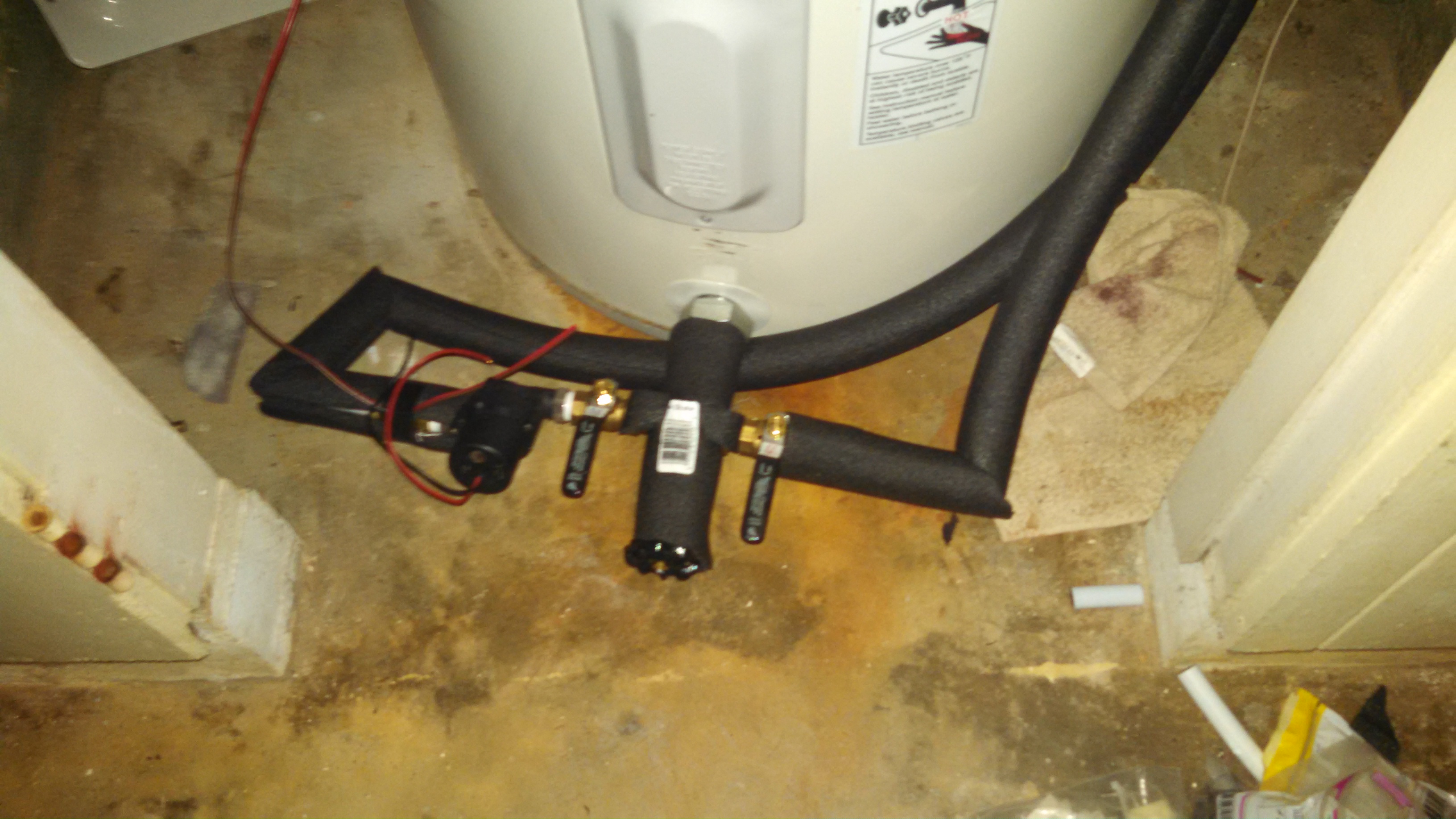
Plumbing the panels with PEX turned out to be relatively uneventful. I decided to route both pipes up the same side of the water heater, because that side of the closet is less likely to get stuff stored in it. Having a brass elbow on either side made a convenient isolated temperature sensor point (more below). I slid the foam insulation onto the pipe end-wise, rather than opening the perforation on the side, in order to keep it from opening on the turns.
There is an Intermatic mechanical timer which turns on the electric to the water heater from 5 PM to 7 PM, the idea being that if the tank is below about 105 degrees F at 5 PM, the electric will boost the temp for evening showers. If the tank temp is above 105, the built-in thermostat will prevent the electric heaters from turning on.
Thermal Sensors
I had already done various things with DS18B20‘s and Raspberry Pi, it’s an easy, reliable way to instrument something for temperature. For the water heater app, I put sensors on the water lines to and from the panels, and on the wall of the tank, which can be accessed through the heating element access panels on the water heater. YOU SHOULD NOT WORK INSIDE THOSE PANELS BECAUSE YOU WILL LIKELY GET YOURSELF KILLED. Take that advice seriously. You cannot work inside the access panels on the water heater without contacting the electrical connections. Unless you understand completely what I am saying, and how to remedy the situation, don’t screw around inside your water heater. If you’ve got a gas heater, you are on your own.
I used more Coax-Seal to stick the sensors to the tank, and electrical tape to hold them on the first brass elbow away from the bottom feed connector. I originally put two sensors on the outer extents of the hot and cold sides of the BFC, but there was insufficient thermal isolation, and considerable thermal inertia in that big piece of metal. Sensors on the BFC gave the impression that the cold side was warmer than the hot side, whereas the first elbow on either side, set apart from the BFC by about 6 inches of PEX, shows that the hot return from the panels is always warmer than the cold to the panels. This is a great source of comfort. Another probable advantage of measuring at the elbow is that it may benefit from some turbulence on the turn, which breaks up laminar flow and gets a better thermal coupling to the temperature of the water in the pipe.
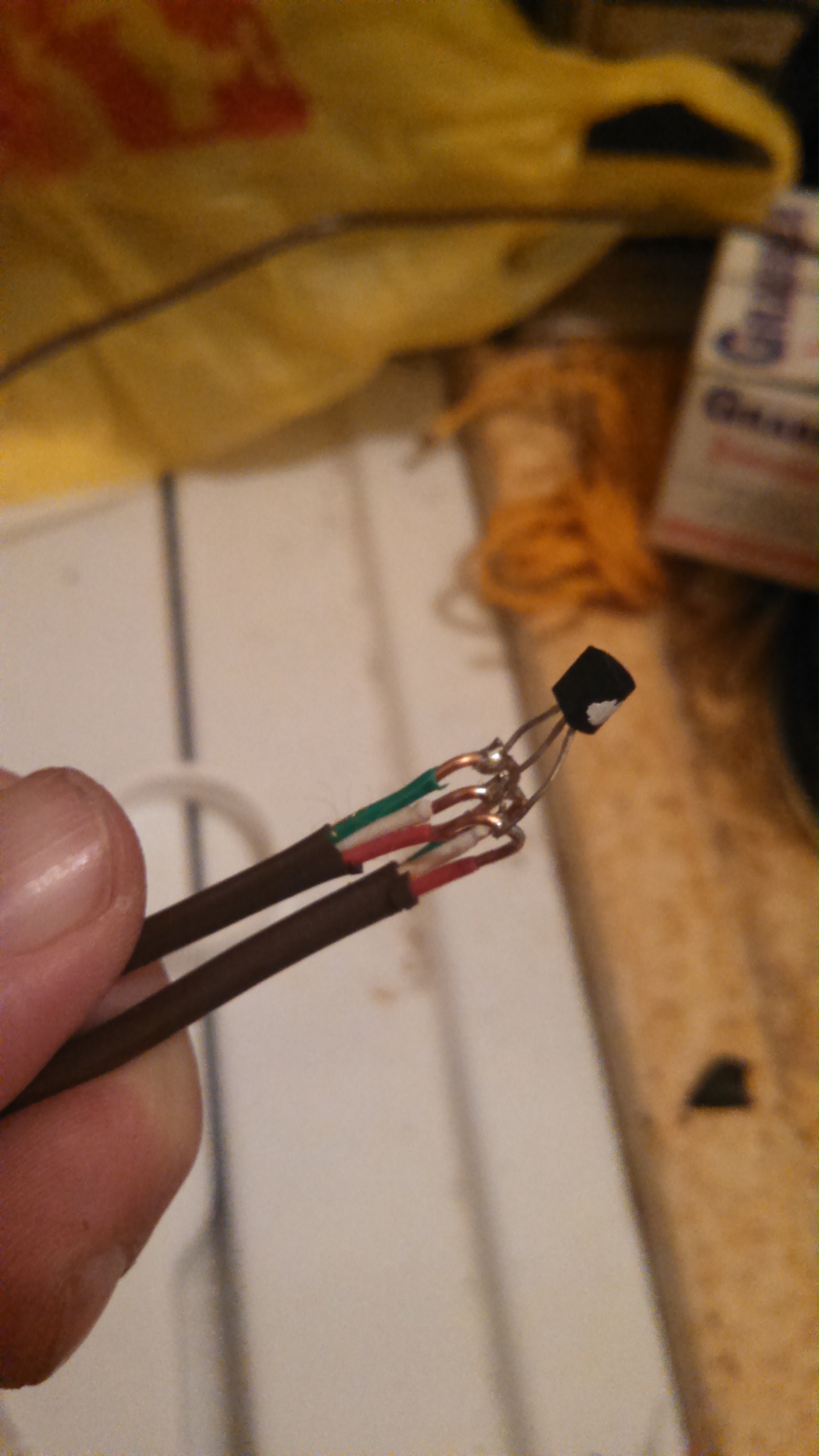
After doing a project with DS18B20’s and CAT5 networking cable, I shifted to 18 gauge thermostat cable, which I got at Lowe’s in a 500 foot roll for about $80. I placed each sensor on the uncut cable by middle-stripping it as shown in the pic, and then hooked the ends of the sensor’s 3 legs to wrap and solder onto the cable. I insulated the result by threading electrical tape between the conductors, but I think that when I plan ahead more, I will use epoxy on each sensor. I tend to work things so that I can put the flat side of the TO-92 case on the thing to be measured, although any side is probably as good.
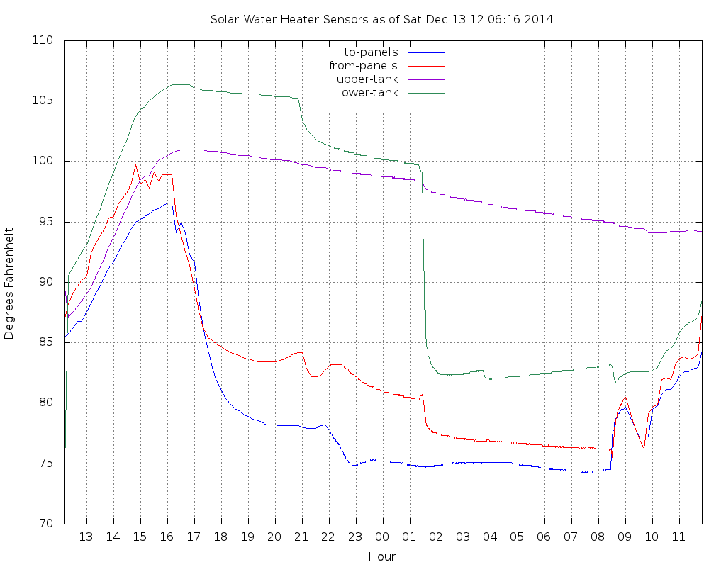
A sample graph above — you can see that the lower tank, somewhat counter-intuitively, stays warmer than the upper tank, after the day’s solar heating, and the first shower (~21:00) causes a drop in the lower tank, because that’s where the cold water supply enters the tank. The apparent temperature inversion could be in some part due to laminar flow of buoyant warm water inside the tank, Of course, the hot output is drawn off the top of the tank. The second shower, at about 01:30, is considerably more voluminous (not to mention names), and causes a precipitous drop in lower tank sensor temperature of 18 degrees F, while the top sensor only declines about a degree or two. The above shows two partly-sunny days in a row, without any really aggressive solar heating.
The Raspberry Pi reads the sensors once per minute, during nominal daylight hours, and once per 5 minutes when it’s dark. The graph shows some interesting changes, probably due to thermal diffusion, which leads to siphoning, etc. Heat loss from the tank seems to be in the range of 2 to 3 degrees F over 6 hours, which of course varies proportionally to the differential between inside and outside.
The solar loop began operation in early December, which is of course, in the northern hemisphere, probably the least effective time in terms of sun angle on the panels, and also among the least sunny times of year in Hawaii. The sunniest day so far brought the upper tank to about 115 deg. F. It’s likely that by March the yield will be significantly higher. A contigency plan is to add a thermostatic mixer valve on the water heater output, to regulate the scalding potential on the output. Solar water heating in Hawaii can sometimes be too effective…
After reading about a couple of folks having power supply damage, I paid particular attention to the PS. Mine has a slightly bent tab on the chassis, hard to say what shock it took. If it tests good, I’ll call it a power supply. Note that you can test a switching PS with a multimeter, but you may have to load it to turn on the output transistors, otherwise there you might measure not-12V output on a perfectly good power supply.
Additional note: the input voltage selection switch on my PS is set to 220V. In order to use it in the U.S., Canada, Mexico, or Japan, it needs to be switched to 110V.
Now we wait for shipment 2…
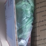
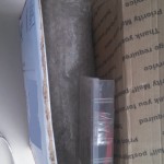
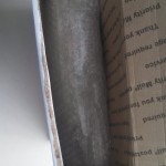
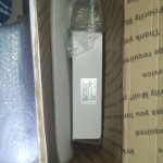
An unboxing gallery:
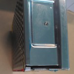
Compressed corner of power supply is lower-left, near side in this photo.
Immediately after opening flap with built-in pull string.
Removed one air sac, exposing hot-end, and beyond.
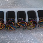
Next mystery blob turned out to be the motors.
Hexagon hot-end kit.
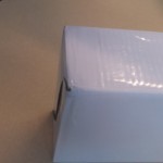
Lastly the power supply. Compressed corner is top right, far corner.
full view of PS carton.
Compression on corner of PS carton.
Slightly deformed tab on PS chassis. Coincides with compressed corner on PS carton.
I realize that somewhere, probably multiple somewheres, there is a blog post, or webzine article with this same title, which espouses the opposite opinions from mine. The great thing about a free society is that being wrong is not illegal. Actually, being wrong is seldom illegal, not nearly illegal as often as being correct, but let’s let that dog lie.
I am compelled to rant about the things that bother me about web sites, and although some are perfectly understandable, they are still disagreeable. So here is my list of things that I hate, when arriving at your web site. Please correct them.
1) Your mobile version sucks. I came to your site to interact with the functionality I interacted with yesterday from my office. I don’t want your astonishingly-bad sub-subset of things that you think mobile users (clue: mobile users are the same people as desktop/laptop users) “want”. Your surveys are badly designed, your focus groups are helpless morons, who didn’t have an opinion until you asked them, and then only invented one out of the vain hope that their “voice” would be “heard”, and your mobile site is a worthless piece of crap. Get rid of it, and build a main page that works well in all the browsers you can find. I have a dual core smartphone with pinch zoom and I can use your “main” site just fine, unless you put some Flashy/Ajaxy/JScripty nonsense in there that don’t play on a touch interface.
2) I don’t want to install your app. I have an app to view your website, and it’s called “browser”. On my dual core smart phone, I have limited space, and I can’t remember what all the apps I already installed do anyways, I’ll be visiting your site with “browser”. Get over it. Stop pushing your app up my nose every time I visit your site.
3) I don’t care to read your rules for posting and the fact that I would have to sign up to post, or view anything beyond text, in the landing view. This is because I, like 99.999999% of your visitors, came to your site through a Google/Bing/DuckDuck search, to read this specific article, and if I don’t see it in about a screen-full of of scrolling, I’m gone. Swish. Outta there. I won’t remember your ugly little site, and I will be careful to avoid accidentally clicking on, or even reading your ads.
4) Don’t prevent resizing in your “mobile” view, it’s annoying. In fact, see #1.
5) Don’t offer me an opportunity to serve you by presenting an opportunity to let you serve me better by filling out a short survey. Your survey is un-answerable, full of leading questions to make me mis-represent opinions on things I don’t have opinions about. Your survey provider is raping you and stealing your money. Get rid of them, they have turned business into a bunch of self-obsessed teenagerish anti-personalities, and I decline to participate. Please don’t pretend that your survey is to “serve me better”. You can shove your survey.
5) If you run a chain of brick-and-mortar stores, offer a brick-and-mortar focus on your web site. Make it possible for me to find out what’s in the store, without having to pick through your on-line specials and — God forbid — your “marketplace” client-vendors who aren’t even related to your company. I would like to visit your store and spend money there, but I’m not even going to get to your store if your competitor shows me what I want first. I hope this happens, and teaches you a lesson.
6) Don’t pop up a “would you like to chat with a help person?” box in front of what I was reading. I was poking at your site, getting to know it. I don’t want to “chat” put that opportunity in a nav panel somewhere where I can ignore it (forever).
7) In fact, don’t put anything up, suddenly, in front of what I’m reading. I will do my best to avoid seeing what’s in the pop-up anyway, since I don’t reward bad behavior.
8) DO NOT EVER auto-play, especially with sound, your video content on your landing page. It compels me to frantically find the tab with your web page in it and close it immediately, and never visit your site again.
All that said, if you present a pleasant experience, I will totally click on your ads. It’s a good feeling to see something in an ad banner that interests me, and then give my click to a good web site. But if you annoy me, I’ll tab out and Google the advertiser.