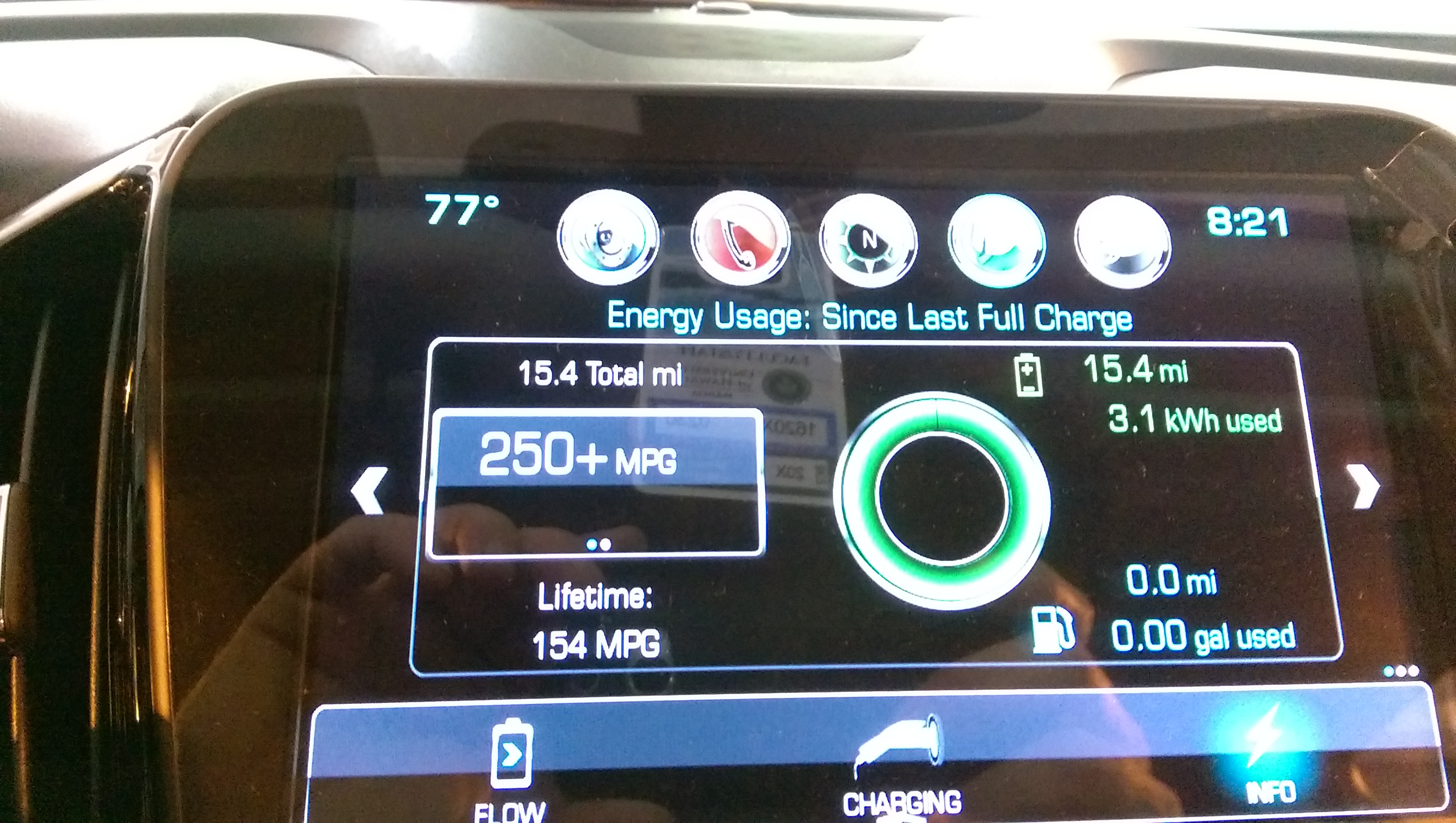
After driving 15.4 miles, the battery range is only 3 miles short of a full charge.
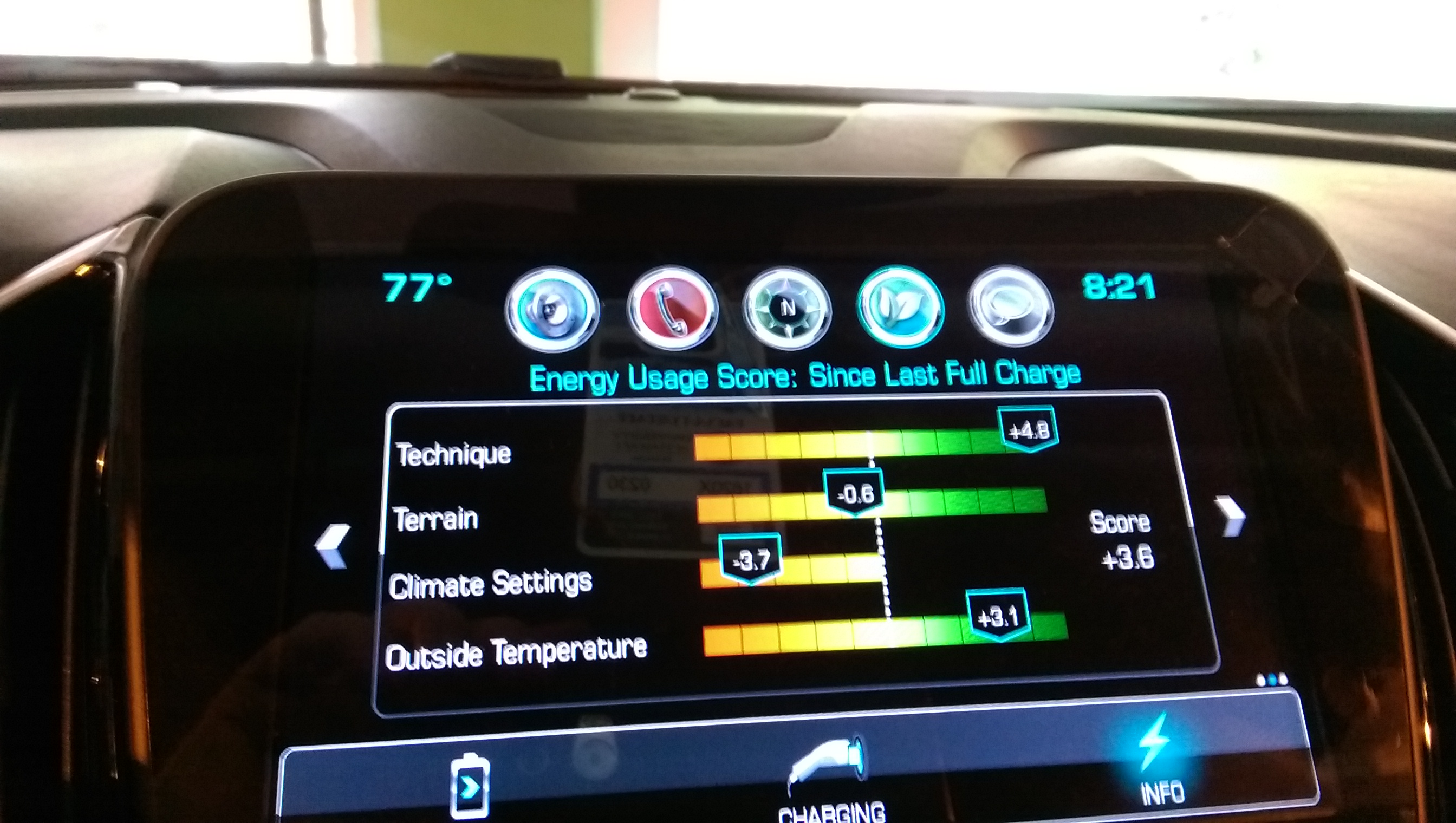
Today was the 4th day driving my 2017 Volt over a mountain range to get to work. I’ve realized something. Although people seem to consider electrics and hybrids “wimpy” or something, and one sees a certain number of conspicuous Priuses (“Priae?”) and Leafs (“Leaves?”) driving meticulously up the steep side of the Likelike Highway, it isn’t in general because they’re underpowered. It’s because they’re instrumented. Driving any of the electrics or hybrids I’ve been inside, one is face to face with the cost of one’s driving habits. When the dealer gave me Volt last week, someone had turned the climate controls all the way to the coldest setting. It took me a while to correct this, and my climate score is still only recovering.
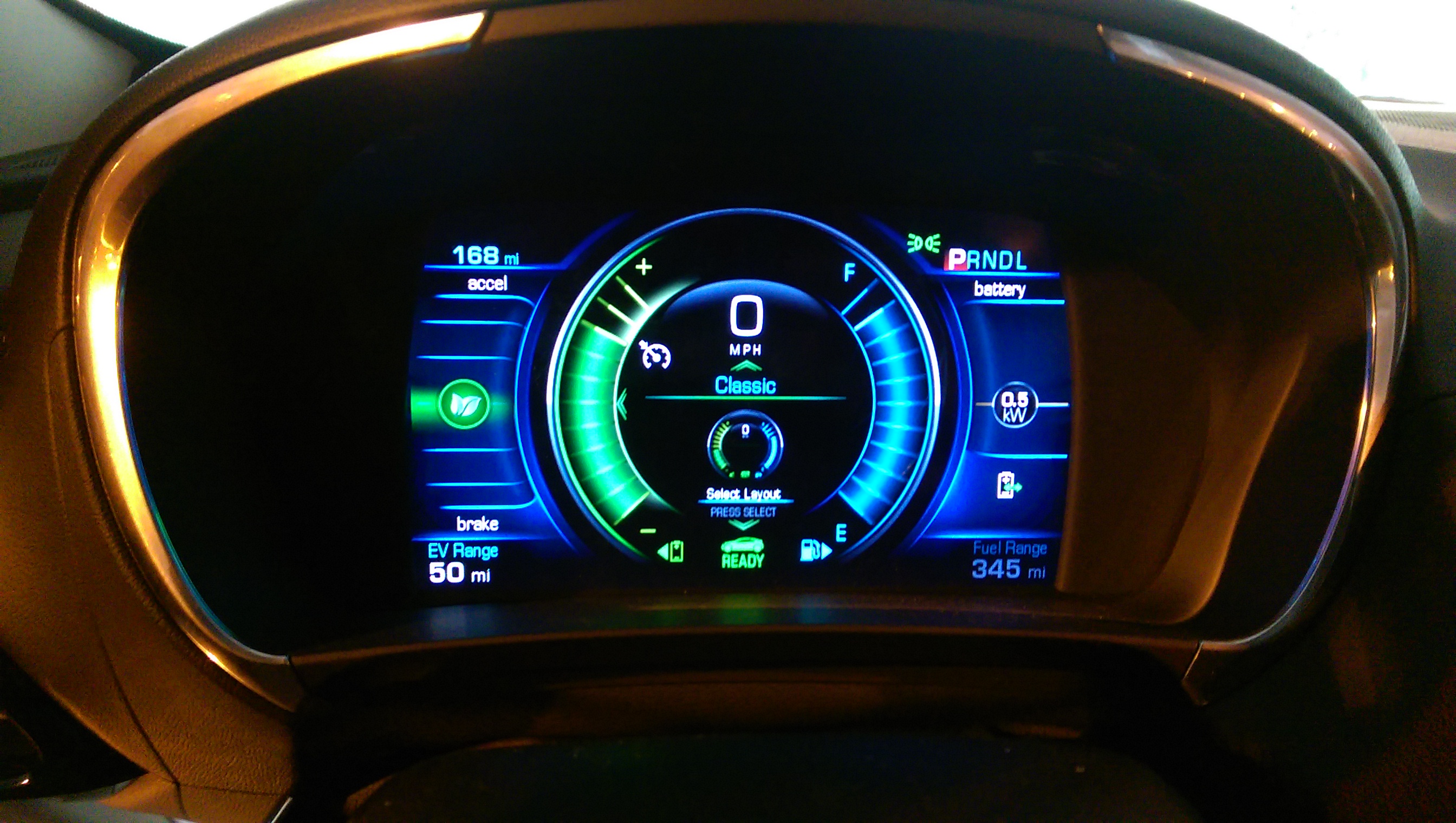
But today’s big kudo to self is for making judicious use of cruise control on the uphill side and regen-on-demand on the downhill side, to finish my 15.4 mile commute with 50 miles electric range showing on the panel. When I crested the hill, the remaining electric miles was 39, but it got back to 50 by the time I reached the parking garage.
Of course, what it means in real numbers remains to be seen, but it shows the game that’s afoot. Today was also the first day I collected ODB2 info on the Volt, it’s interesting to see the KW used at different points along my route.
Judging from the recent increase in new faces around the Google+ Cobblebot Community, there are numerous kits reaching backers, and many of them undertaking the build. Some have come up against the firmware config and compile/upload as confusing. I had done Arduino stuff before, and although I’m new to 3D printing, I have worked as a prototyper engineer in the past, designing and building and making electro-mechanical things work, so I may not realize what it’s like to start from scratch. Still, I think that this build is do-able for most people with the inclination. There have been claims made, to the effect that the parts are simply too terrible to work, or that the design is so flawed that it’s hopeless. Both of these are clearly not true, no more than claims by the company that the parts they supply are adequate.
My printer is built with as few mods as possible. The things for which I “rolled my own” are:
I replaced the stack-o-bearings idler pulleys with these.
I contrived my own spring-loaded bed-leveling system.
I mounted endstops, which the official instructions glossed over.
I added a fan to the hot-end heat sink, with tie wraps.
I added spiral cable binding, tie-wraps, and a salvaged electronics enclosure
I added a few screws and t-nuts, which I bought extra from OBPS.
Other than that, I used what was supplied by CobbleBot, and I’m making progress in getting print quality to a useful level.
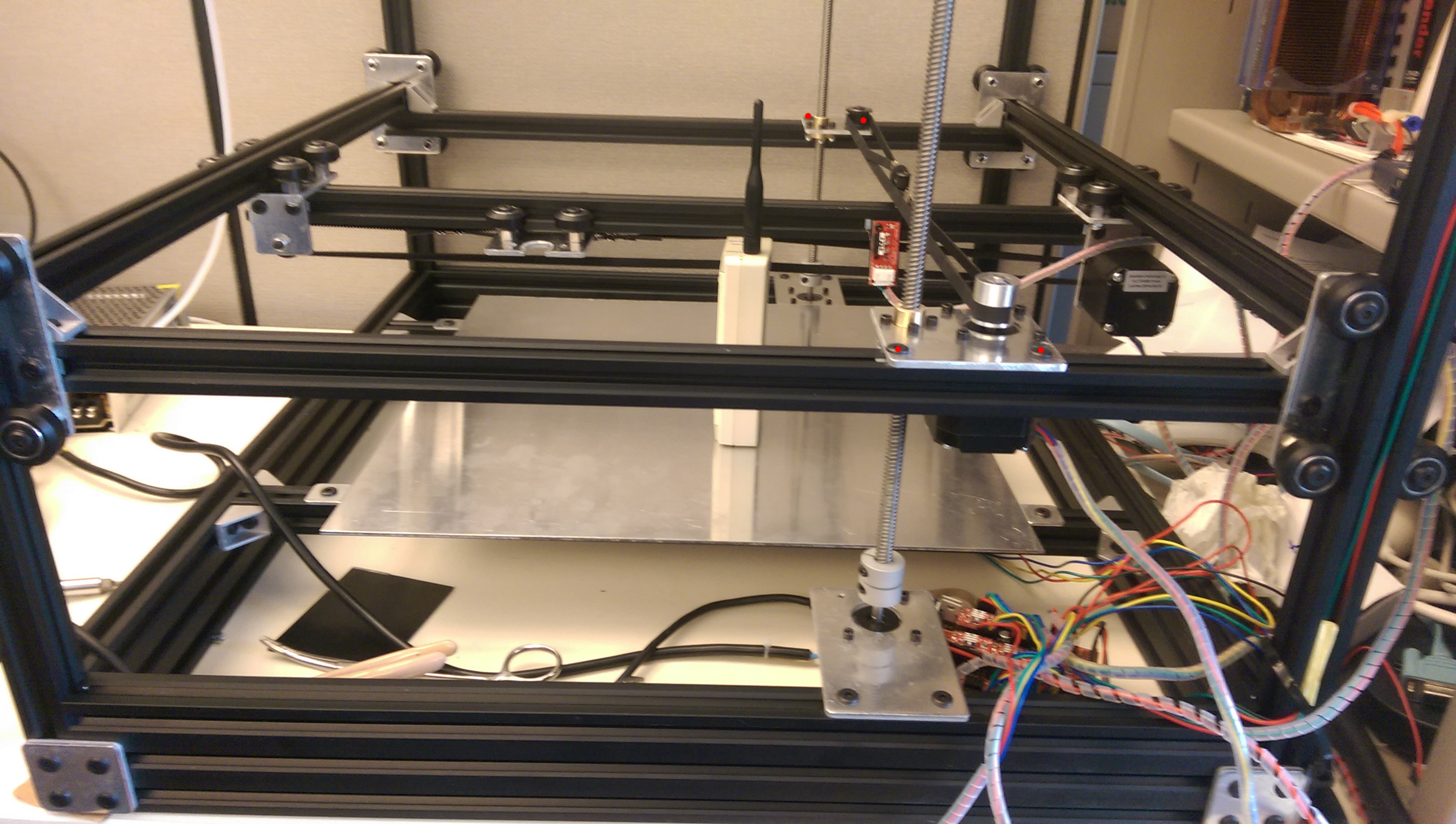
My CobbleBot has the following characteristics:
Z-motors are at the top. This was pretty easy to do, and I did it because there tends to be binding in the lead screws when the motor coupler gets close to the nut. If this binding happens at bed level, then you’re screwed. If this binding happens at the top of the travel, your build height is limited, at some point. With my bed mounted above the tops of the base rails, I’m currently getting 270 mm of free Z travel.
Z endstop is at the bed level. For a long time, I had it at the top, but one spends an awful lot of time slewing to bed level after a homing procedure. I had thought of using things like (Marlin) mesh bed leveling or (Marlin/Repetier FW) numeric auto-leveling, but the setups for those things all assume that Z home is at the bottom. Also, Slic3r inserts this “raise nozzle to 5mm/lower nozzle” thing which is great with bottom-homing, but less so when home is at the top and the “raise nozzle to 5mm” is actually a lower-nozzle-265 mm at breakneck speed.
I also put 10 mm M5 screws into t-nuts under each Z-gantry where the gantries should be at Z-home, so that there is a hard-reference for Z-gantry-levelness. NOTE that when you drop t-nuts into the vertical rails, you should put a pencil or something in the groove at to top of the base rail so that the nut doesn’t simply disappear into the base rail at the bottom.
X and Y endstops are at MAX.
This just sort of turned out this way. I chose to reverse the direction of Y, to make coordinate zero be in the front. For X I forget. But the endstop placement for X and Y seems to be a lot more arbitrary than it is for Z.
(This is a work in progress. It may already contain useful stuff, so I’m publishing it. Expect further — ask questions in the Google+ Community).
Raw notes follow:
I received the second box of 2 on June 6, 2015. I got:
DRV4988’s (red versus DRV8825’s which are purple),
white “acetal” wheels. Mine were pretty reasonable, not full of some of
the defects I’ve seen on others’. Still, to fit the bearings into the
wheel took a lot of force.
metal plates, even though I don’t think I selected them as an
upgrade
one of two push-fits for the bowden PTFE tube was 5mm (4mm is required)
The build instructions are available at Cobblebot.com. Log in, search
for “Cobblebot Basic Hardware Assembly Guide” (or whatever version you
have). You need to purchase the instructions for $0.00.
==========================================
Tools:
allen wrenches:
At least a set of metrics, with 1.5 mm, 2 mm, 3mm.
I found that I wanted both the loose L-shaped set,
as well as an insertable bit to put in a screwdriver-style
handle. A motor driver might be good — not a drill, but a
gearmotor screwdriver. Drills are too fast and too powerful.
Open-end wrenches:
3 mm
10 mm
Wire cutters (side-cutters/dyke-cutters)
Needle nose pliers (or maybe big tweezers).
===========================================
Little heat sinks.
I bought little heat sinks for my stepper drivers —
Which appear in my pictures. You may wish to get some of these also.
They come with peel and stick adhesive on the back to stick them on the
chips.
I bought a batch of DRV8825, too —
which come with heat sinks, but no adhesive to attach them. Luckily, I
have enough of the other heat sinks to supply them all.
===========================================
Screw specs;
M5, 0.8 thread pitch — most of the frame assembly
M3, 0.5 (?) thread pitch — lead screw nut mounting screws, extruder
bracket to M3 T-nut, and any screw that screws into a motor body.
M4, 0.7 – extruder spring screw (I had to replace the nut, got one at local HW store)
The M3 screws for mounting the extruder bracket on the frame would be better off as hex-head (as in turnable with a crescent wrench, rather than an allen wrench), so you could tighten them from the side.
I found M5 x 0.8 screws at Lowes in the little drawers, and M4 x 0.7
screws/nuts/washers (part of the extruder at a local Hawaii hardware store called City Mill.
==========================================
For the lead screws, I and at least one other builder have found white lithium grease to work well. Not too messy, once you’re done touching the lead screws, so maybe lubricate after the build.
==========================================
When building gantries, I found that a little white lithium grease in
the eccentric spacer holes was a good thing.
When you put the gantries together, initially rotate the eccentrics with a 10mm wrench, so that the wheels are as far apart as possible. You can rotate them to go tighter on the rails later.
My rule of thumb is that I should *just* be able to rotate the wheel with my thumb and forefinger when its engaging a rail. You may find that there are places where the inside wheels are really tight, and the outside are loose, or vice versa. It’s always good during construction to have assembled things semi-tight, meaning not prone to slipping, but slip-able under a little force, so you can work things up and down, or right and left, etc and let them find their place in the world, followed by full tightening.
==========================================
If you are missing wheels: see this Google+ thread:
If you get no wheels, you need wheels.
The bearings that Cobblebot sent us do not work well with the shims that
Cobblebot sent us. The above discussion covers this.
With appropriate shims
(such as: http://openbuildspartstore.com/mini-v-wheel-precision-shim/)
the Cobblebot bearings *might* work OK, or you might get most of them
working and need a couple, or you might just want to buy 28 of these,
which include everything you need for the wheels EXCEPT the M5 x 25mm screw:
http://openbuildspartstore.com/solid-v-wheel-kit/
If you order wheels, or whatever, consider getting a bag of tee-nuts:
http://openbuildspartstore.com/tee-nuts-25-pack/
Plus, there are these — t-nuts that can be inserted into the groove
without sliding in from the end, but I thought they were too expensive…
http://openbuildspartstore.com/drop-in-tee-nuts/
The Bowden extruder pushfit deficiency:
https://plus.google.com/113777585643345712764/posts/gwboiQzGim9
Your kit should include two small brass fittings, which slip onto the
PTFE tubing that guides your filament from the filament extruder motor
to the hot end. I received one which is for 5mm tubing, which had a
black release button, with a “5” imprinted on the button. The ones that
are correct for 4mm PTFE tubing tend to have blue release buttons, and
have a “4” imprinted on the button. Cobblebot acknowledged the
deficiency in an update, but says that they plan to ship replacements
after all printers are shipped. You should open a ticket if you got the
wrong pushfit connector.
I obtained a replacement from Amazon:
“PC4-M6 Pneumatic Straight Fitting for 4mm OD tubing M6 6mm Reprap 3D
Printer etc”
I built my CB with the first draft instructions, but the second were
tl;dr for me, but note:
You need to insert the following t-nuts before assembling the related rails:
In the base 20 mm x 60 mm, long sides, place 4 t-nuts on the inside of
each of two longer rails. Typically these are in the top groove, but you
can put them lower, to increase build height. These will support the
90-degree brackets to hold the bed supports.
In the base 20 mm x 60 mm, short sides, place 2 t-nuts on the top edge
of each of the two shorter rails. These will connect the Z drive motor
plates to the frame. (This assumes that you are going to mount the Z
motors at the bottom. I moved mine to the top. But if you bought more
t-nuts, you don’t care. :^) )
On the shorter, lower rails that make up the Z gantry square, put 2
t-nuts into the top edge groove on each of two rails.
Illustrations — red dots at locations of relevant t-nuts, assuming some
x-ray vision.
(CDMA time standard radio not included with Cobblebot)
The Blog re-sized these pictures so that they kind of suck. I will work on that.
ALSO: you will need to insert 3mm t-nuts (of which you may have precious
few) for endstops, and for the extruder mounting.
=========================================================
Cable Organization
You need to pick a spot where your Arduino/RAMPS are going to reside.
This is probably best-off in the back, to keep the cables out of your
face, and it works well to mount the assembly on the top rail. This will
help in routing cables to the hot end, which needs 3 pairs — the heater
power, the thermistor sensor, and the heatsink fan power. You may also
consider a fan to cool the print, and to that end, if you route a cable
for the hotend fan, use cable with at least two pairs in it.
Getting the Z gantry assembly (with X and Y already installed into it)
to fit onto the vertical rails.
I had to build it with the cross-rail screws semi loose, so I could fit
it onto the 4 uprights and get the spacing right, and then tighten one
(kit 1A) or both (kit 1B) to fix the width.
(need pictures to clarify WTF I’m talking about).
====================================================
As far as the SD card reader and LCD are concerned, I’ve done nothing
with them, yet. Early on, I plugged it in and the Arduino wouldn’t boot,
so I abandoned them for the time being. You don’t need them to print,
and even if you want them, you’re probably better off using a host
software like Pronterface or Repetier Host to get your CB working.
=====================================================
Assembling the extruder:
Do what Mike Kopack says in this video (it’s not completely obvious):
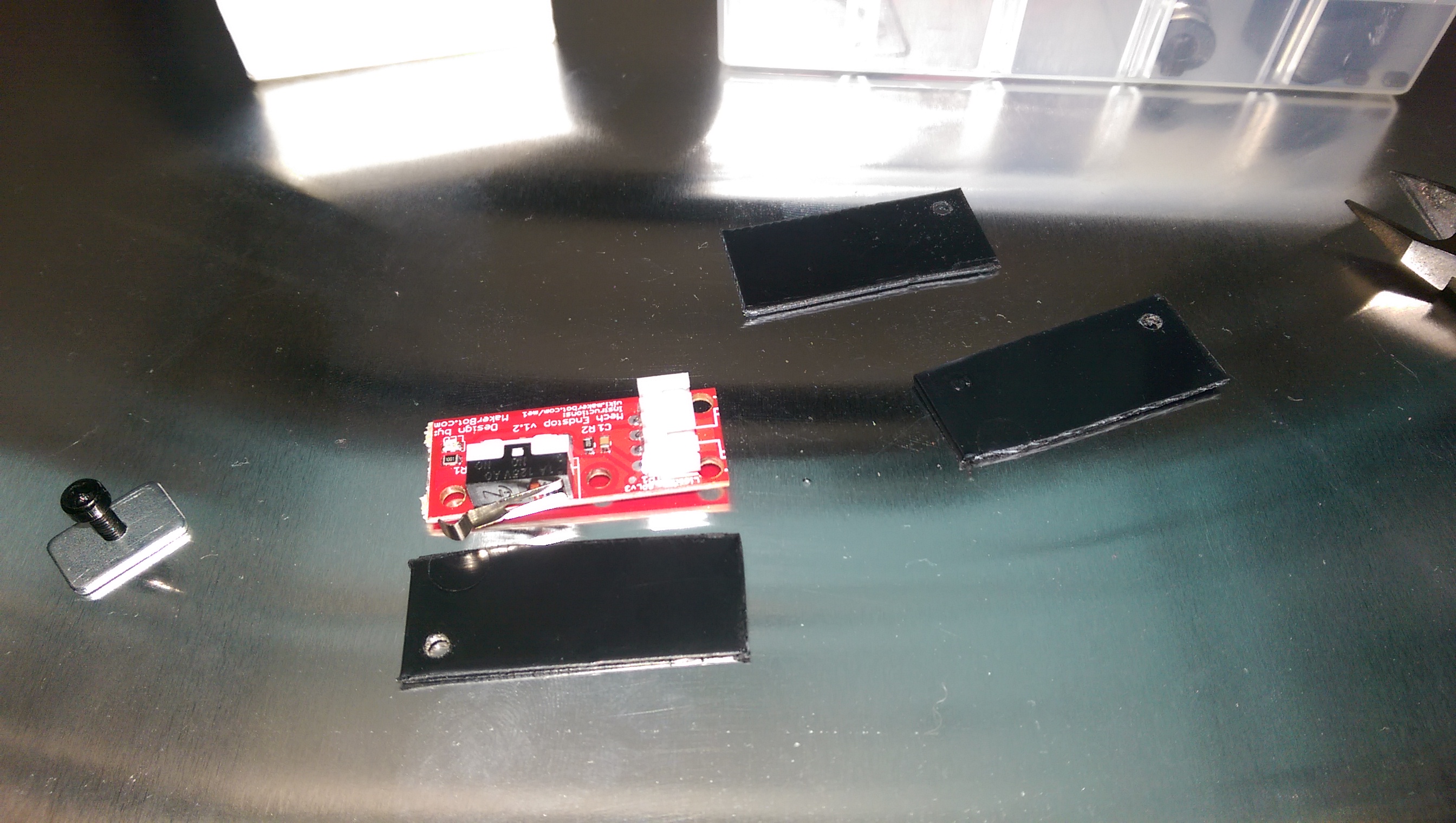
The Official Instructions are notably lacking and somewhat obtuse
regarding endstops. They suggest putting electrical tape on the solder
side, and then putting endstops at “the minimum” on each axis.
Electrical tape is an *unspeakably* *shitty* idea, don’t do that.
I made plastic plates by cutting up dividers from those annoying little plastic drawer parts cabinets, with scissors. (Really tired of people telling me to “just 3D print it” when I didn’t have my 3D printer built yet). Notable that there’s only one hole on the endstops where you can put a mounting screw. I may bootstrap my endstop mounts now that I can print tolerably well.
(need pictures to clarify WTF I’m talking about)
I originally set up Max endstops on all three axes, but in the end, I
moved the Z endstop to the bottom.
I have endstops that contact wheels, but I can see that over time, the
rotation of the wheel will distort the lever on the limit switch. It is
better to contact gantry plate edge or rails than it is to contact wheels.
Do this:
http://www.marlinfirmware.org/index.php/Setup
I am using Marlin 1.0.3dev (use the “Latest Development version” in the
above tutorial.)
Your should find these lines in the file “Configuration.h” and change
them per the following (assuming you have DRV4988 stepper drivers (red). If you have DRV8825 drivers (purple), the DEFAULT_AXIS_STEPS_PER_UNIT numbers will be something like double) :
#define MOTHERBOARD BOARD_RAMPS_13_EFB
#define CUSTOM_MACHINE_NAME “Cobblebot Basic”
#define EXTRUDERS 1
// Or if you have 2 extruders, you can put “2”.
// but I suggest getting one working first.
#define TEMP_SENSOR_0 5
// per http://reprap.org/wiki/Hexagon
// IF you find that some motor or other is moving the wrong direction,
// you can affect that here:
// Invert the stepper direction. Change (or reverse the motor
// connector) if an axis goes the wrong way. Below is how mine are
// YMMV
// below tells Marlin which endstop you are using and what direction an
// axis has to move to reach said endstop
// ENDSTOP SETTINGS:
// Sets direction of endstops when homing; 1=MAX, -1=MIN
// :[-1,1]
#define X_HOME_DIR -1
#define Y_HOME_DIR -1
#define Z_HOME_DIR -1
// You will have to find the following out for yourself.
// When you get so your machine can home reliably, then you can use
// host software to move to extents. If your Z motors are more toward \
// the center, you will have shorter Y, if your Z lead screws start to
// bind at 275 mm, then make this 270. My philosophy has been to get a
// working printer, even if the build volume is a little reduced, and
// and then you’ll be fighting less uncertainty and fewer variables
// in expanding.
// Travel limits after homing (units are in mm)
#define X_MIN_POS 0
#define Y_MIN_POS 0
#define Z_MIN_POS 0
#define X_MAX_POS 311
#define Y_MAX_POS 255
#define Z_MAX_POS 288
// Go gently at first, then try higher speeds later, especially in Z
// Homing isn’t really that critical speed wise — you want to
// home accurately, and then print well.
#define HOMING_FEEDRATE {50*60, 50*60, 4*60, 0} // set the homing
speeds (mm/min)
// default settings
#define DEFAULT_AXIS_STEPS_PER_UNIT {80,80,400,94.5}
#define DEFAULT_MAX_FEEDRATE {300, 300, 16, 25} // (mm/sec)
// I reduced the bejeezus out of Z. It can sound like it’s smooth, but
// miss steps, nonetheless.
=========================
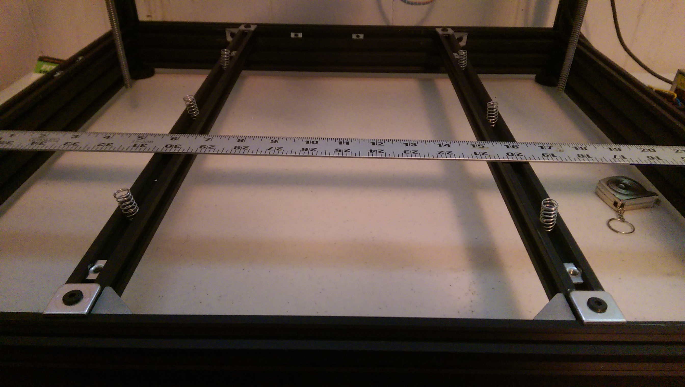
The adjustable print bed
I bought a pack of 6 springs at local hardware store, which slide into the v-slot rails that were provided as bed supports.
Also, I used the square bed mounts provided by CB to support the ends of the rails, so that they just drop in are essentially flush with the top of the base rails. I secured the ends with one 90 degree bracket per end.
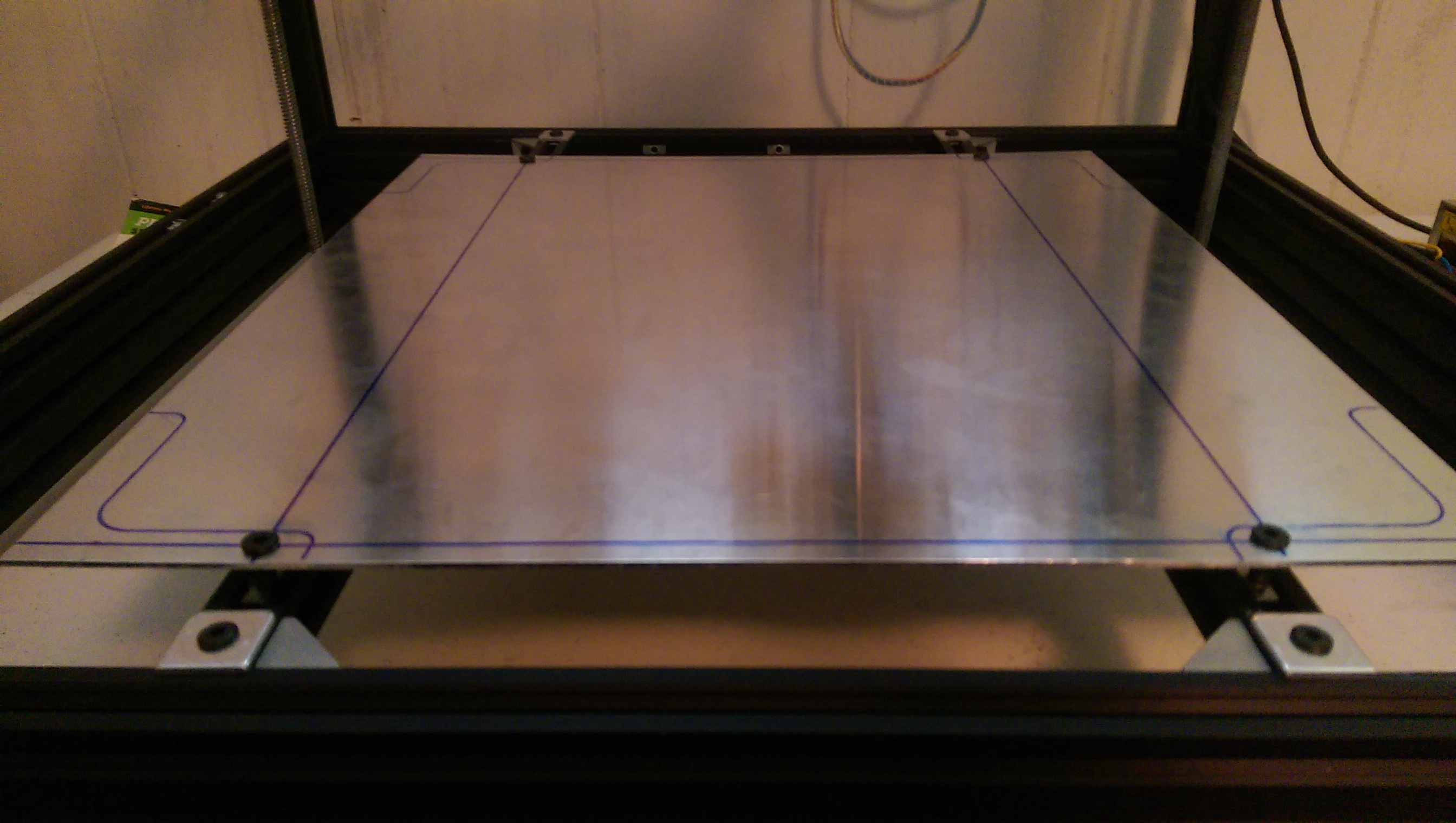
I drilled (like, 6.3 mm) holes the bed so that M5x25 mm screws could engage t-nuts in the rails, and then I drilled corresponding holes in the rails so that the screws have clearance to go deeper, through the rail. I did not put the screw through the spring, but it’s important to keep the end springs next to the screws. If there is space between the screw and the spring, then tightening will warp the bed as it gets toward the bottom of the adjustment.
It will take a couple of rounds to get the bed adjustment to “surround” the Z-gantry error. I recommend setting the Z min endstop with the bed mostly compressed, and 2 or 3 mm of space between the bed and the hot end nozzle. Then you can rotate screws counter-clockwise until the gap between nozzle and bed just barely grips a sheet of printer paper. I have had good luck leveling with my Fleks3D plate sitting on the CB aluminum plate, secured by binder clips. Typically, I adjust for the 4 corners and then the center of my build footprint. My bed layers are mostly flat — if yours aren’t, you may have more hoops to jump through. A sheet of glass (I found some 12×12 mirror tiles that are pretty good) clipped onto your aluminum bed may average things out enough that you can calibrate to the glass and have a reasonably flat surface. So far, my observation is that if the bed is equidistant from where the Z-gantries bring the nozzle, then it doesn’t matter that the Z-gantries aren’t flat. The only complication being that the Z gantry motors can get unsynced, or the frame can be torqued so that it changes. The former seems to be more of a problem than the latter. If the motors are at the same level (measure from the base rail to the lower z-gantry connector rails at each side, and you get a frame of reference for how lopsided it is.
Since I have rails kit 1A, the obvious adjustments to flatten the Z-gantries is unavailable when the gantry cage is assembled. I’ve been tempted to either:
buy 1500 mm of vslot and make longer rails.
OR
Drill the vertical rails to make an access hole to loosen the screw at when the Z-gantries are at the bottom.
When last I printed, I had gotten the bed into a place where I couldn’t raise the bed enough to grip the paper on one corner. I plan to go back and center the bed adjustment in the middle of its range, and then see that the endstop and each of the other 3 corners is bracketed by adjustment, if possible.
Useful to remember that the adjustment screws are 5mm x 0.8 thread pitch, so when you need to move the bed up or down on millimeter, it’s about 1.25 turns. Or 0.1 mm is about one-eighth of a turn, etc.
My caliper says my printer paper is about 0.1 mm thick.
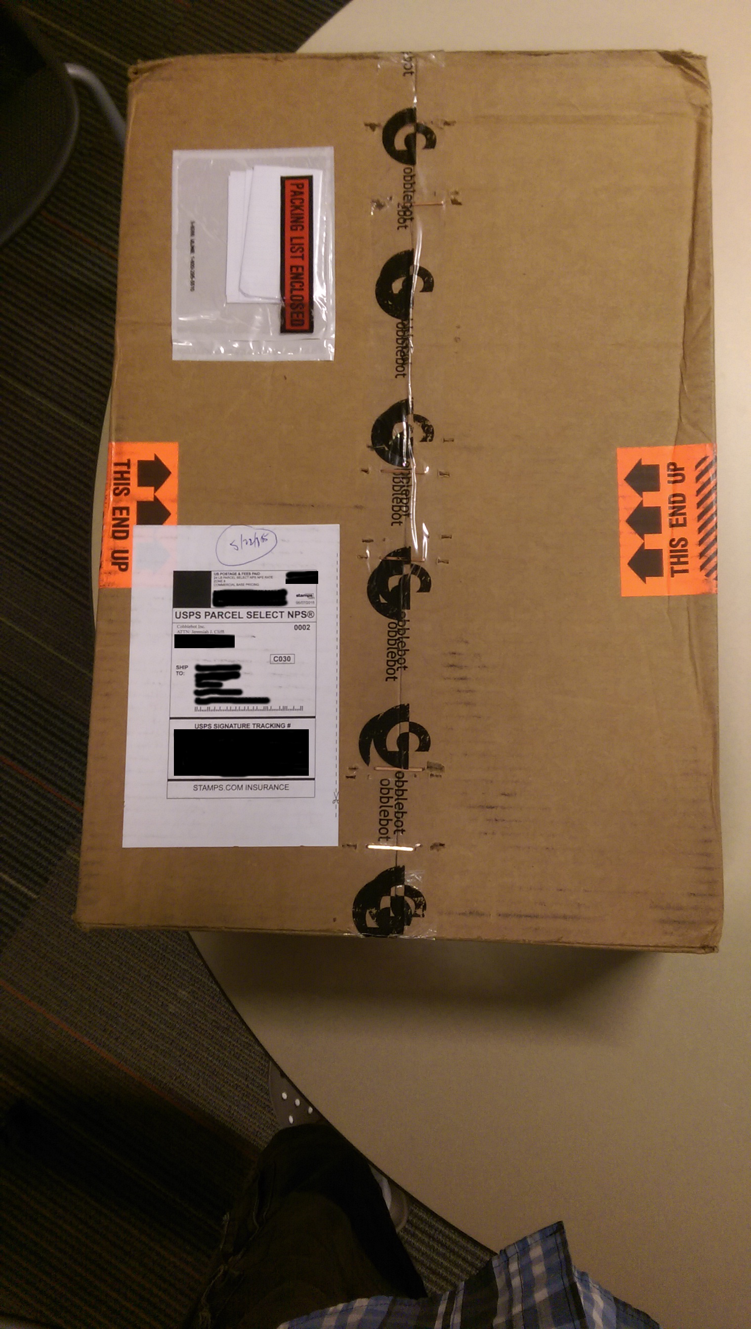
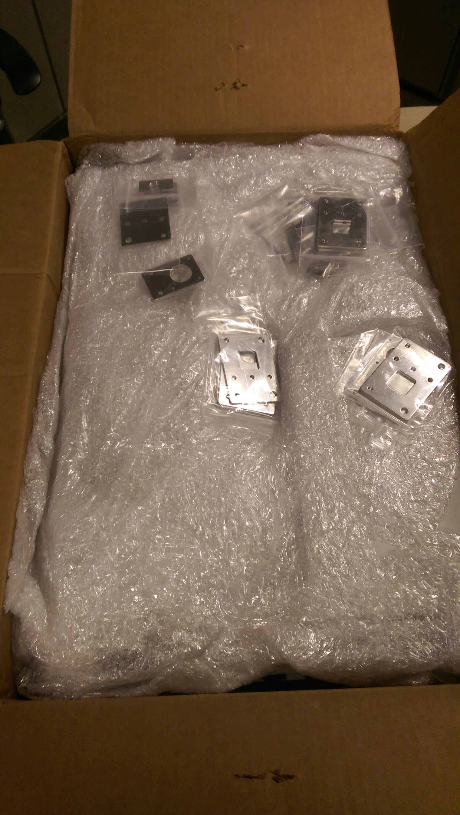
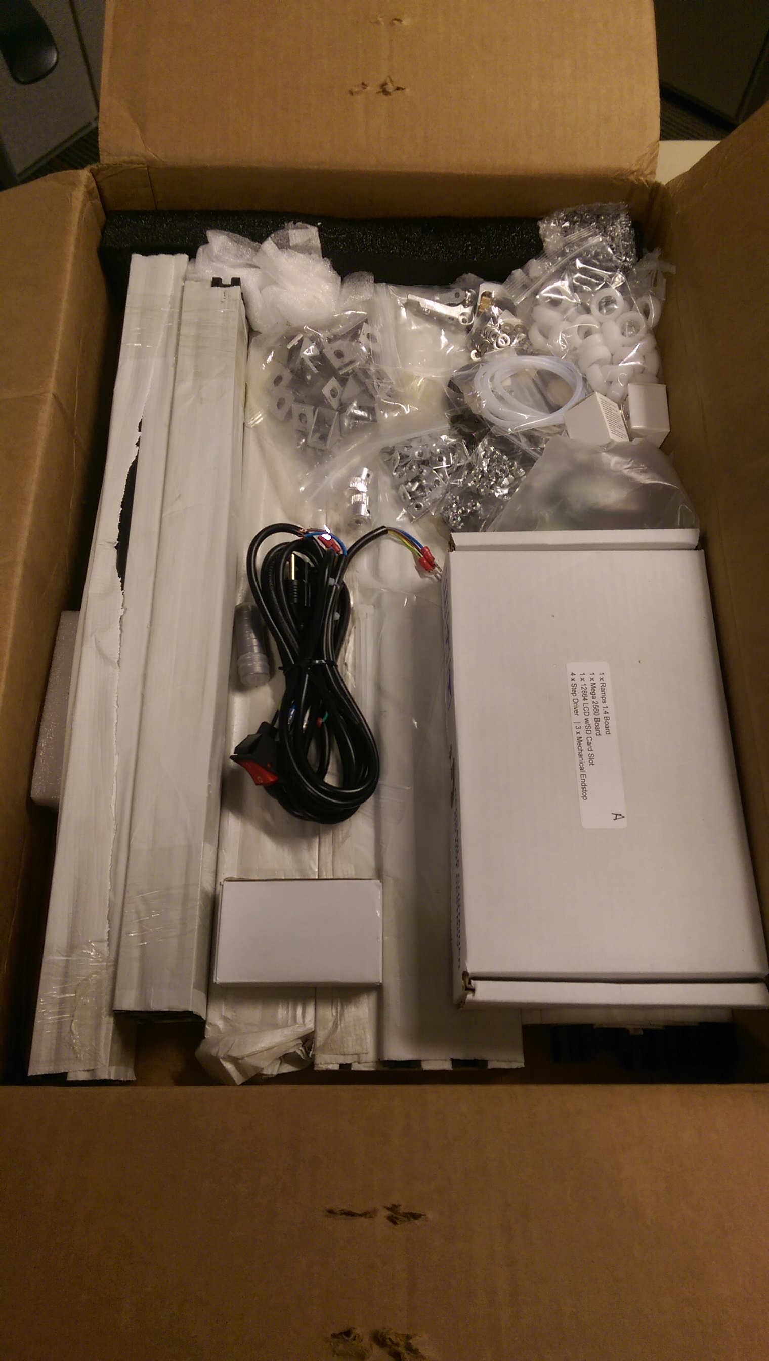
The remainder of Cobblebot came on Friday, right before the 3-day weekend, even though USPS tracking predicted Tuesday after Memorial Day. I did a thorough inventory, comparing to the parts list in the instructions, and found that it is all there, AFAIK, with a few extras not listed in the currently-released build instructions.
On Saturday, I spent time with the electronics, not to build them, but to test them and make a few videos about how they work together. Unfortunately, I’ll need to upload those on Tuesday. I started to upload them from out here at the Lake Cabin, but the Internet connection becomes unusable for other things, and it would take about 12 hours, anyways.
Some unboxing pictures:
I did a complete count, there were a few extra nuts and what-not, but nothing missing…
Amongst the lore of our family is a story, one of several, of my Uncle Smiley, who stated: “When we were living in Florida, we bought 100 feet of black garden hose, and spread it across the roof of the house. We never spent another penny heating water.”
When I got a look at our electric bill for August – $193 – I realized that there was probably good reason to seek out a new way to make hot water. So I followed the vision of the abundant garden hose.
How might one connect The Hose to one’s tank heater? I wondered. This inquiry led me to the Heliatos bottom feed connector (PDF), which led to an appreciation of the EZ system.
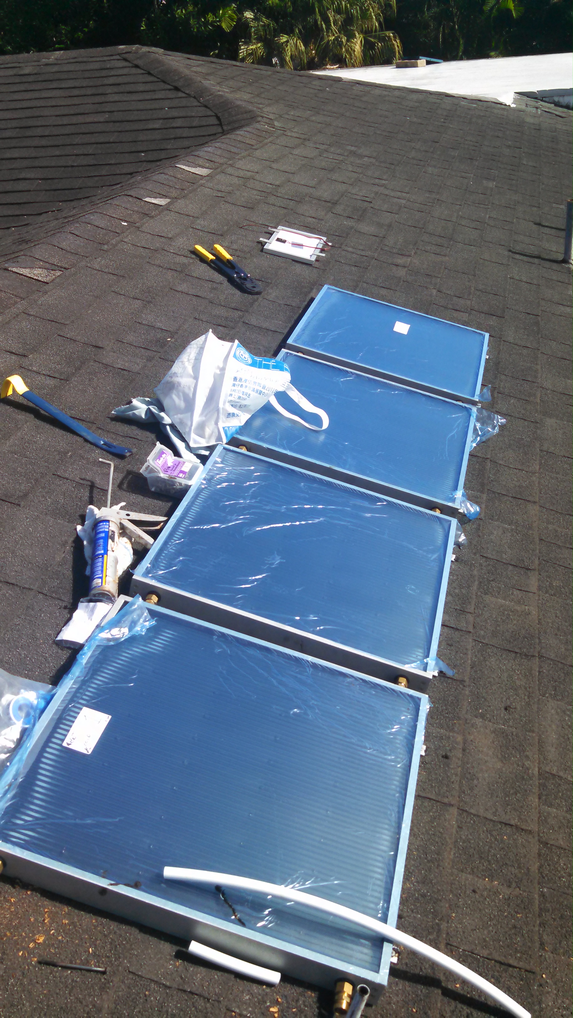
For about $1100, including the tools and accoutrements to be PEX-capable, I got it up there on the roof. The roof offers southwest and southeast faces, I chose southwest, because our hot water needs tend to occur in the evening, and because it puts the panels over the garage, where a leak would be considerably less worrisome.
I actually received the 4 panel EZ system in September, but then I had two out-of-town trips coming, so doing new plumbing seemed unwise. I hate getting a call about something gone awry at home when I’m away, and when I do, it’s better when I am not the direct cause. An additional advantage to waiting was that my wife was leaving town for two weeks, November/December, and the prospect of having a no-hot-water interval at home during the install was easier to bear with her somewhere else.
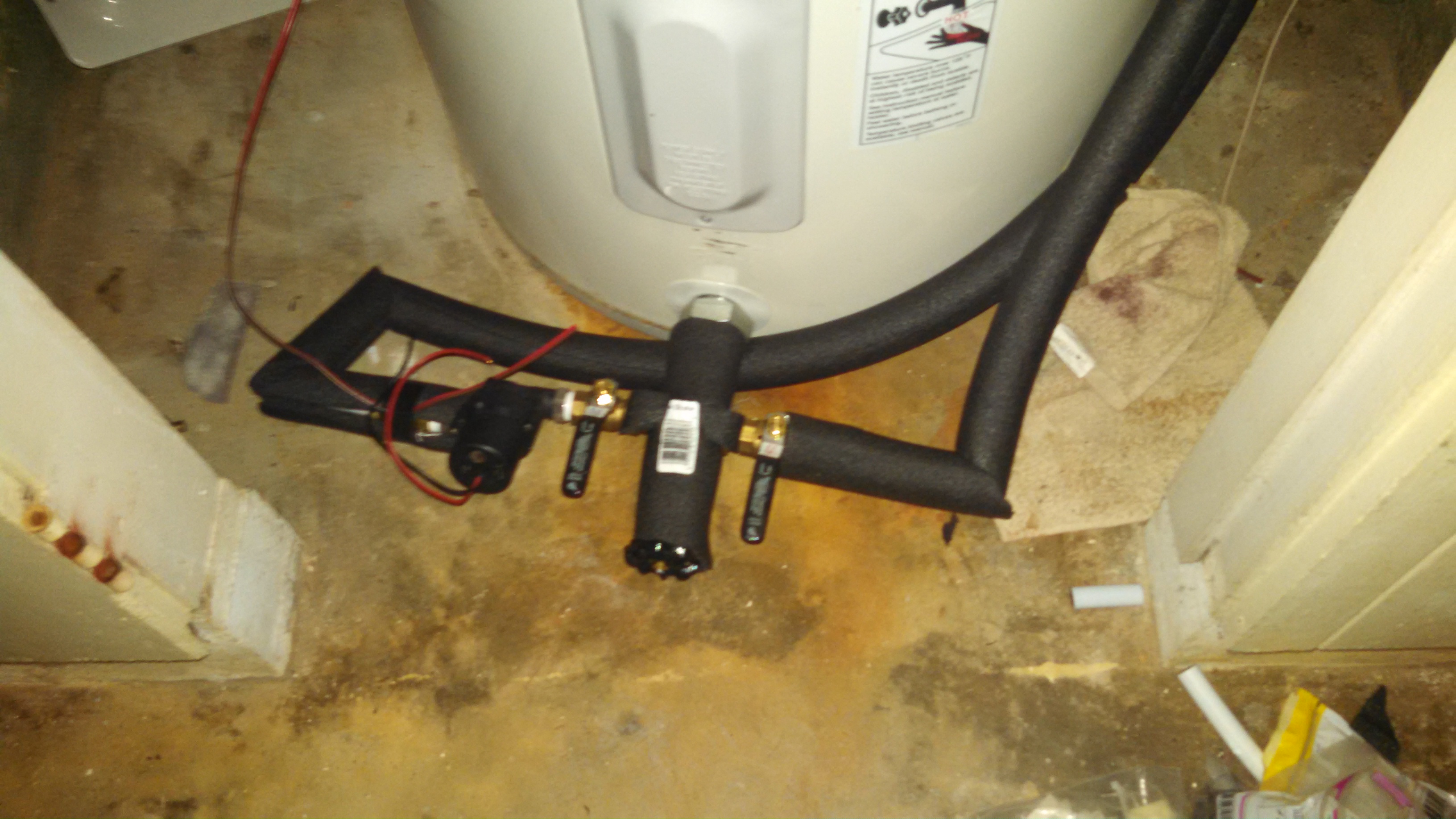
I got the bottom feed connector installed the evening of Thanksgiving Day (after enjoying a lovely buffet at the Hale Koa). I had sort-of-dreaded this step. Existing plumbing doesn’t always follow your plans, especially in the humid salt air of Hawaii. Luckily, this water heater is only about 6 years old, and everything’s still pretty shiny. I had let the tank cool for a couple of days, which gets showers down to about skin temperature, to avoid flushing too much money down the drain, before draining the tank. In retrospect, I should have planned to do a proper clean and flush, by removing the bottom heating element and spraying the mud in the bottom of the bottom of the tank, but there’s no reason I can’t still do that.
The installation of the BFC was, in fact a little dicey due to the fact that the only part of the internal nipple assembly visible outside the insulation was the threads on the union, so I had to devise a way of turning the thing to acceptable tightness without hurting the threads. I put several wraps of teflon tape on the boiler end and turned it in, first with a piece of leather between the pipe wrench and the threads, and later just turning gingerly with the wrench teeth on the threads themselves. Luckily the boiler threads were pretty clean and easy to turn into, and also the type of union used in the BFC has a rubber gasket that acts as the water barrier, so nicking the threads on the union isn’t quite the problem it would be on regular tapered pipe threads. Somehow, the BFC fits inside the water heater closet door, without modifications, something I spent time assessing and worrying about.
The interconnection of panels, per instructions, took probably a couple of hours, and I did the better part of half of the work downstairs, by finishing the left side of each connection, leaving only the right side to complete on the roof. At one point, my skim of the instructions left me with the impression that the connectors on the last end of the last panel should be connected together, but it turns out that they need to be capped. If I had made that mistake, the panels would have been curiously ineffective, and it probably would have been frustrating to diagnose and fix. The design of the panels relies on the water flowing bottom-to-top through the panels, which is a slightly more resistant flow path than a pipe, so adding a pipe on the end would effectively bypass the panels. I think that ideally things should flow bottom-to-top, since the heat-diffusion-based flow of the water in the panel would assist, and I think that if you reversed the pipes, the detrimental effects might not be noticeable.
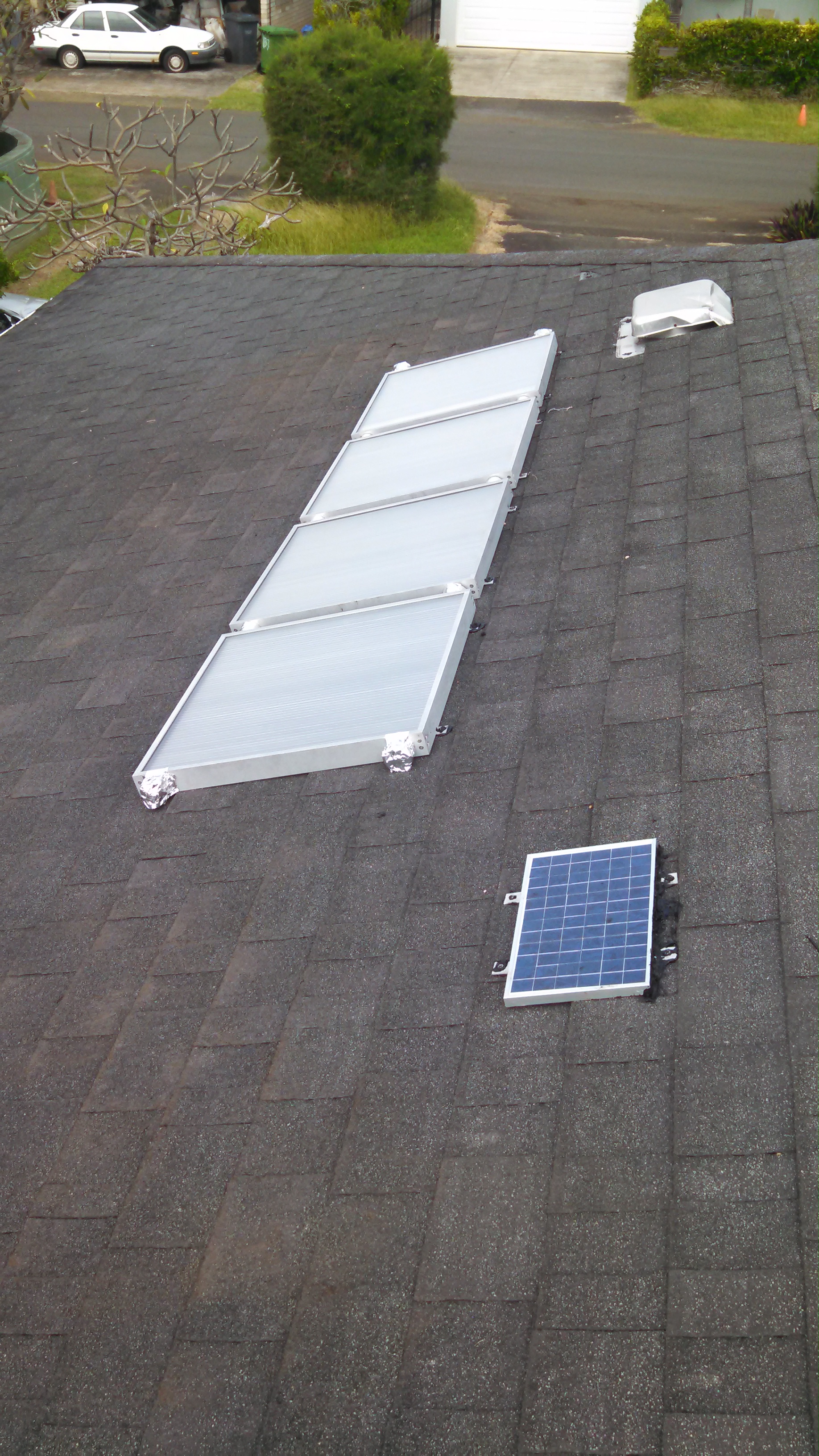
I thought and read a lot about panel mounting, and I finally ended up just squirting a pillow of roofing sealant into each mounting bracket and then deck-screwing through the sealant, shingle, and roof boards. I was blessed with two days of hard rain immediately following the install, which produced no drips.
One flurry of squirreliness occurred around the installation of the PV panel. They give you the panel, some wire nuts for the pump motor end, and 25 feet of wire. The connection for the panel end, however is neither well thought out, nor easy. There are two solder points to connect the wire, and two screws holding the little metal tabs to the panel body. The connection point is covered by a little plastic slide cover, which allows enough room for, well — nothing. One could try to simply use the screws with crimp-lugs, but the screws are inclined to thread in once, and any removal and re-install makes a not-very-connected connection against the metal of the tabs. I ended up soldering the connectors, and then smooshing a ball of Coax-Seal into the connection box, to exclude water, which seems to have worked. I also ran a bead of roofing sealant along the top of the panel to direct water around the panel when it rains.
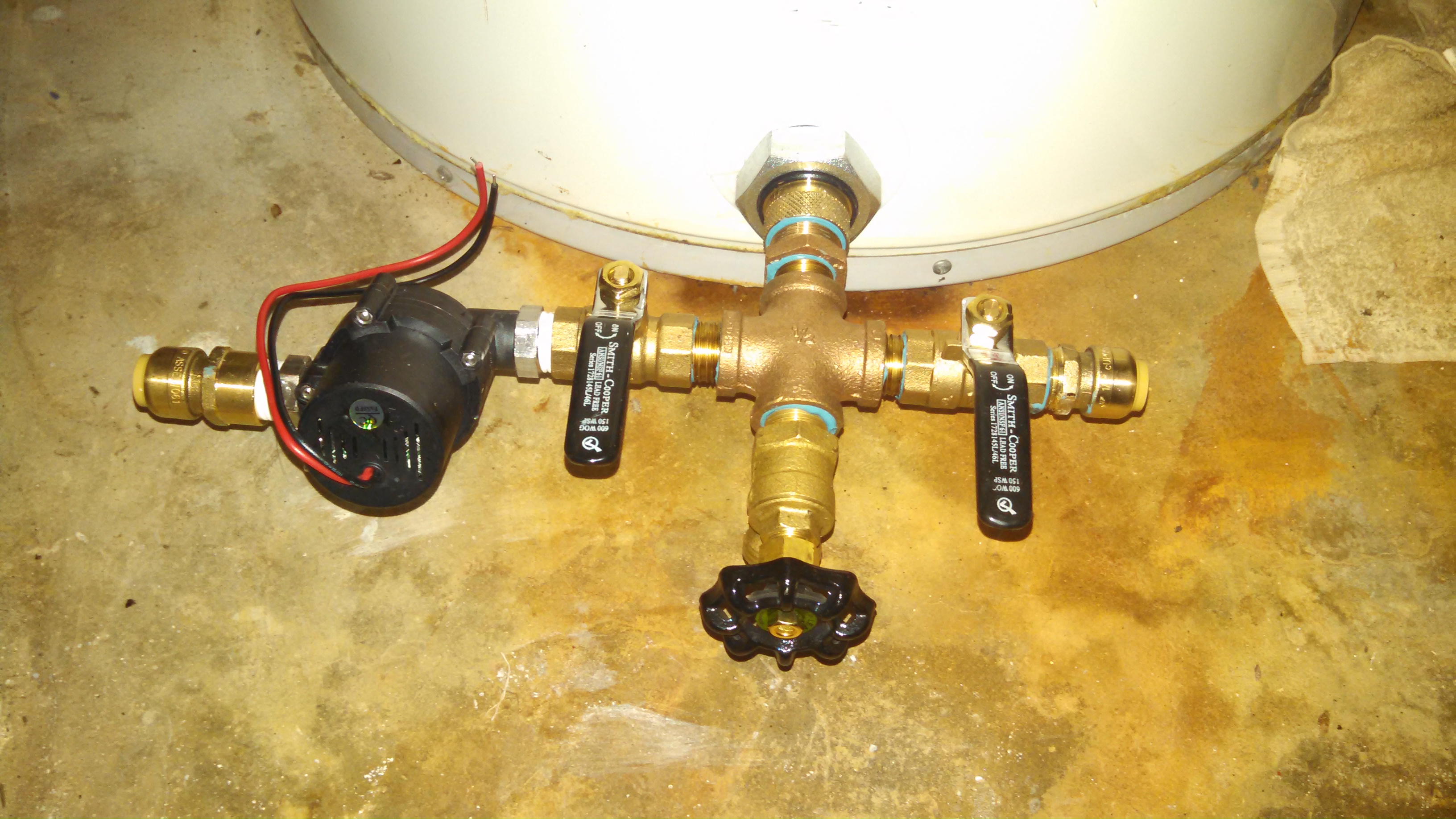
Plumbing the panels with PEX turned out to be relatively uneventful. I decided to route both pipes up the same side of the water heater, because that side of the closet is less likely to get stuff stored in it. Having a brass elbow on either side made a convenient isolated temperature sensor point (more below). I slid the foam insulation onto the pipe end-wise, rather than opening the perforation on the side, in order to keep it from opening on the turns.
There is an Intermatic mechanical timer which turns on the electric to the water heater from 5 PM to 7 PM, the idea being that if the tank is below about 105 degrees F at 5 PM, the electric will boost the temp for evening showers. If the tank temp is above 105, the built-in thermostat will prevent the electric heaters from turning on.
Thermal Sensors
I had already done various things with DS18B20‘s and Raspberry Pi, it’s an easy, reliable way to instrument something for temperature. For the water heater app, I put sensors on the water lines to and from the panels, and on the wall of the tank, which can be accessed through the heating element access panels on the water heater. YOU SHOULD NOT WORK INSIDE THOSE PANELS BECAUSE YOU WILL LIKELY GET YOURSELF KILLED. Take that advice seriously. You cannot work inside the access panels on the water heater without contacting the electrical connections. Unless you understand completely what I am saying, and how to remedy the situation, don’t screw around inside your water heater. If you’ve got a gas heater, you are on your own.
I used more Coax-Seal to stick the sensors to the tank, and electrical tape to hold them on the first brass elbow away from the bottom feed connector. I originally put two sensors on the outer extents of the hot and cold sides of the BFC, but there was insufficient thermal isolation, and considerable thermal inertia in that big piece of metal. Sensors on the BFC gave the impression that the cold side was warmer than the hot side, whereas the first elbow on either side, set apart from the BFC by about 6 inches of PEX, shows that the hot return from the panels is always warmer than the cold to the panels. This is a great source of comfort. Another probable advantage of measuring at the elbow is that it may benefit from some turbulence on the turn, which breaks up laminar flow and gets a better thermal coupling to the temperature of the water in the pipe.
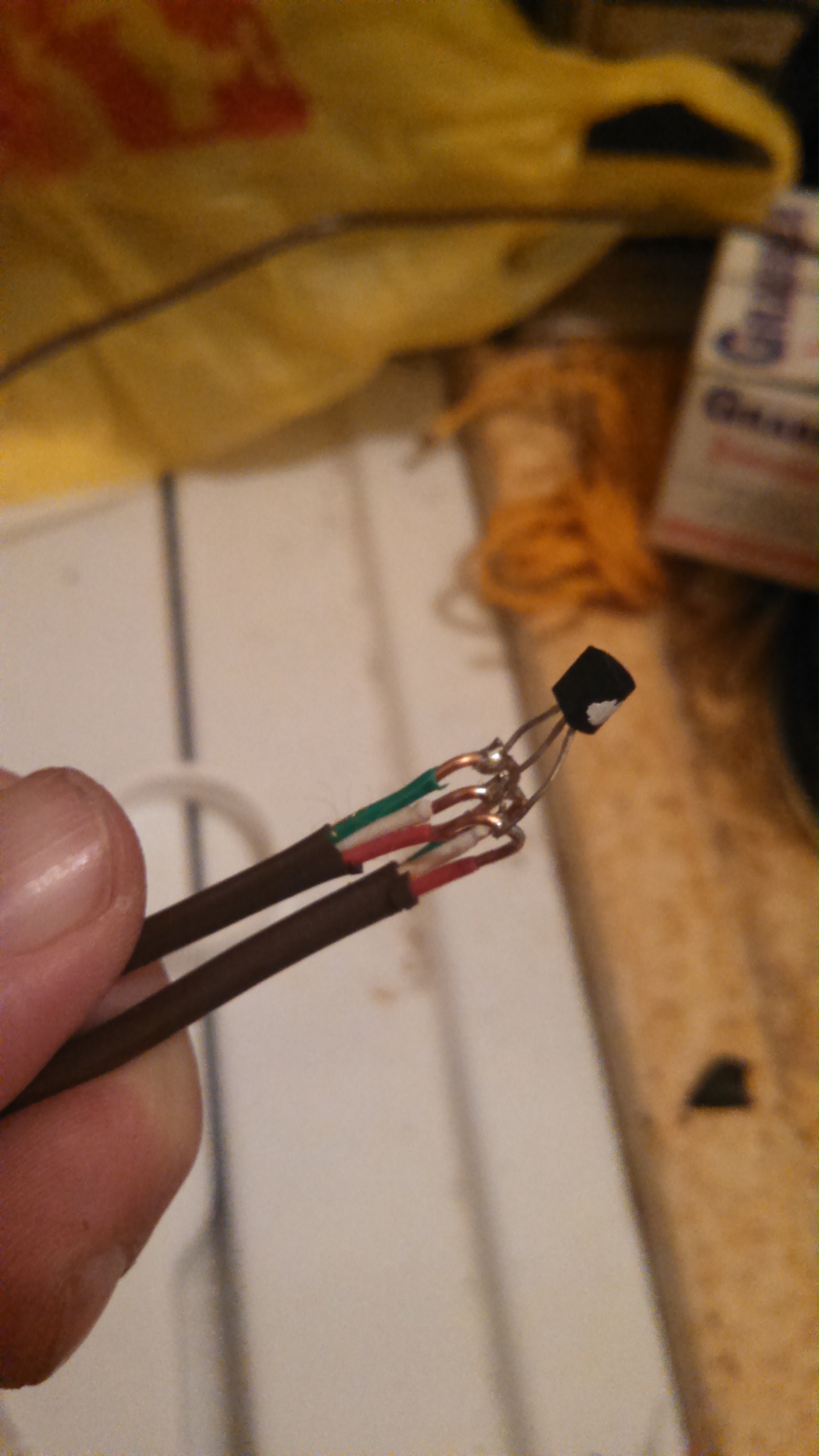
After doing a project with DS18B20’s and CAT5 networking cable, I shifted to 18 gauge thermostat cable, which I got at Lowe’s in a 500 foot roll for about $80. I placed each sensor on the uncut cable by middle-stripping it as shown in the pic, and then hooked the ends of the sensor’s 3 legs to wrap and solder onto the cable. I insulated the result by threading electrical tape between the conductors, but I think that when I plan ahead more, I will use epoxy on each sensor. I tend to work things so that I can put the flat side of the TO-92 case on the thing to be measured, although any side is probably as good.
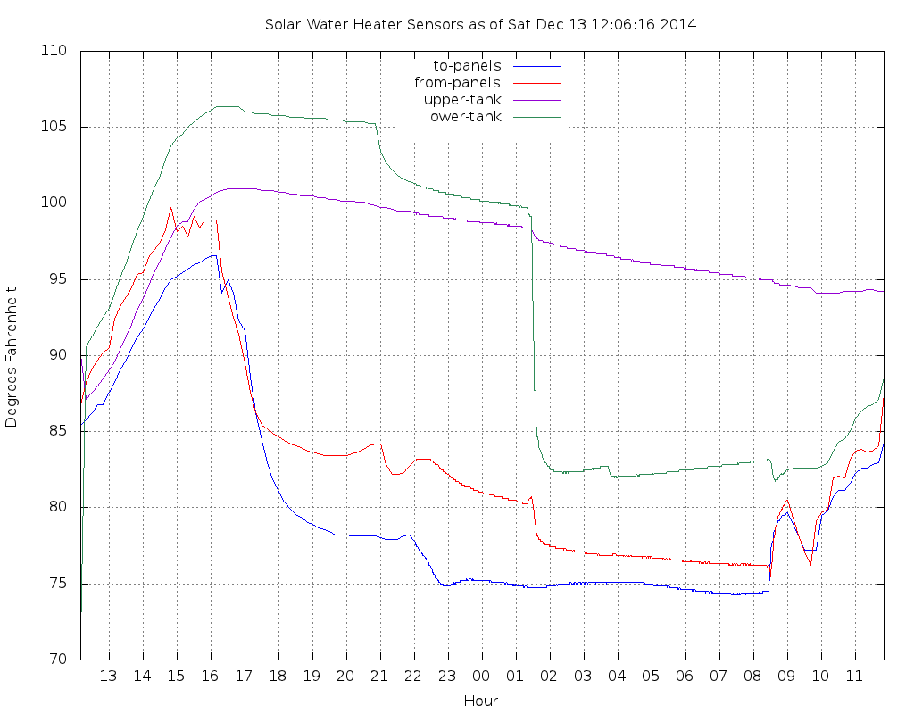
A sample graph above — you can see that the lower tank, somewhat counter-intuitively, stays warmer than the upper tank, after the day’s solar heating, and the first shower (~21:00) causes a drop in the lower tank, because that’s where the cold water supply enters the tank. The apparent temperature inversion could be in some part due to laminar flow of buoyant warm water inside the tank, Of course, the hot output is drawn off the top of the tank. The second shower, at about 01:30, is considerably more voluminous (not to mention names), and causes a precipitous drop in lower tank sensor temperature of 18 degrees F, while the top sensor only declines about a degree or two. The above shows two partly-sunny days in a row, without any really aggressive solar heating.
The Raspberry Pi reads the sensors once per minute, during nominal daylight hours, and once per 5 minutes when it’s dark. The graph shows some interesting changes, probably due to thermal diffusion, which leads to siphoning, etc. Heat loss from the tank seems to be in the range of 2 to 3 degrees F over 6 hours, which of course varies proportionally to the differential between inside and outside.
The solar loop began operation in early December, which is of course, in the northern hemisphere, probably the least effective time in terms of sun angle on the panels, and also among the least sunny times of year in Hawaii. The sunniest day so far brought the upper tank to about 115 deg. F. It’s likely that by March the yield will be significantly higher. A contigency plan is to add a thermostatic mixer valve on the water heater output, to regulate the scalding potential on the output. Solar water heating in Hawaii can sometimes be too effective…
I realize that somewhere, probably multiple somewheres, there is a blog post, or webzine article with this same title, which espouses the opposite opinions from mine. The great thing about a free society is that being wrong is not illegal. Actually, being wrong is seldom illegal, not nearly illegal as often as being correct, but let’s let that dog lie.
I am compelled to rant about the things that bother me about web sites, and although some are perfectly understandable, they are still disagreeable. So here is my list of things that I hate, when arriving at your web site. Please correct them.
1) Your mobile version sucks. I came to your site to interact with the functionality I interacted with yesterday from my office. I don’t want your astonishingly-bad sub-subset of things that you think mobile users (clue: mobile users are the same people as desktop/laptop users) “want”. Your surveys are badly designed, your focus groups are helpless morons, who didn’t have an opinion until you asked them, and then only invented one out of the vain hope that their “voice” would be “heard”, and your mobile site is a worthless piece of crap. Get rid of it, and build a main page that works well in all the browsers you can find. I have a dual core smartphone with pinch zoom and I can use your “main” site just fine, unless you put some Flashy/Ajaxy/JScripty nonsense in there that don’t play on a touch interface.
2) I don’t want to install your app. I have an app to view your website, and it’s called “browser”. On my dual core smart phone, I have limited space, and I can’t remember what all the apps I already installed do anyways, I’ll be visiting your site with “browser”. Get over it. Stop pushing your app up my nose every time I visit your site.
3) I don’t care to read your rules for posting and the fact that I would have to sign up to post, or view anything beyond text, in the landing view. This is because I, like 99.999999% of your visitors, came to your site through a Google/Bing/DuckDuck search, to read this specific article, and if I don’t see it in about a screen-full of of scrolling, I’m gone. Swish. Outta there. I won’t remember your ugly little site, and I will be careful to avoid accidentally clicking on, or even reading your ads.
4) Don’t prevent resizing in your “mobile” view, it’s annoying. In fact, see #1.
5) Don’t offer me an opportunity to serve you by presenting an opportunity to let you serve me better by filling out a short survey. Your survey is un-answerable, full of leading questions to make me mis-represent opinions on things I don’t have opinions about. Your survey provider is raping you and stealing your money. Get rid of them, they have turned business into a bunch of self-obsessed teenagerish anti-personalities, and I decline to participate. Please don’t pretend that your survey is to “serve me better”. You can shove your survey.
5) If you run a chain of brick-and-mortar stores, offer a brick-and-mortar focus on your web site. Make it possible for me to find out what’s in the store, without having to pick through your on-line specials and — God forbid — your “marketplace” client-vendors who aren’t even related to your company. I would like to visit your store and spend money there, but I’m not even going to get to your store if your competitor shows me what I want first. I hope this happens, and teaches you a lesson.
6) Don’t pop up a “would you like to chat with a help person?” box in front of what I was reading. I was poking at your site, getting to know it. I don’t want to “chat” put that opportunity in a nav panel somewhere where I can ignore it (forever).
7) In fact, don’t put anything up, suddenly, in front of what I’m reading. I will do my best to avoid seeing what’s in the pop-up anyway, since I don’t reward bad behavior.
8) DO NOT EVER auto-play, especially with sound, your video content on your landing page. It compels me to frantically find the tab with your web page in it and close it immediately, and never visit your site again.
All that said, if you present a pleasant experience, I will totally click on your ads. It’s a good feeling to see something in an ad banner that interests me, and then give my click to a good web site. But if you annoy me, I’ll tab out and Google the advertiser.
“It seems awfully dark for 6:45”, I thought, when the alarm went off. But it had been raining and cloudy last night, so I took it in stride. I got up and answered the Cat’s call for breakfast, set the coffee maker into production, and told my wife it was time to get up.
It took me a few minutes to notice the clock in the living room, which said it was 5:48. Having just woken up, I was skeptical that anything was amiss. It must be me. I looked at my Verizon smart phone, which had served as the alarm that woke me. It said 6:48. I decided that since Hawaii does not observe daylight savings time, I needed to consult a dumb clock, one that had no notion of DST. The bedroom alarm clock said 5:48, the kitchen range and microwave and coffee maker said 5:48.
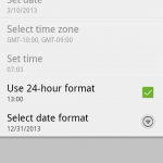
Maybe I messed with the time setting on my phone, I thought. When I looked, it was set to “Automatic – use network provided values”, and time zone “GMT-10:00, GMT-9:00”. I took it off automatic, and set the time to to match the other clocks, and the time zone to Hawaii/Aleutian. Then I clicked on automatic again. It went right back to DST and zone “GMT-10:00, GMT-9:00”. I am now annoyed that some Verizon engineer, who is probably fast asleep, has made this horrific mistake and left me without an hour of Sunday morning sleep. Or perhaps, even worse, some idiot in California, who clicked (or failed to unclick) the DST setting on a CDMA base station somewhere. Thankfully, my multiple CDMA-disciplined clocks on the UH network do not use time zones, and appear to be OK. (BTW: My wife’s T-Mobile phone says agrees with the coffee maker.)
I was lurking on a conference call about a month ago, when the strangest thing happened. A series of touch-tones began intruding on the call, making further conferencing impossible. Since I had destinated at work, I decided to hang up and head for my office.
By Sunday night, three days later, it had become apparent that the Old (Motorola Original) Black Droid just wasn’t what she used to be. There were enough “phantom” touches to render it useless, and after much fiddling, I declared it totaled, and decided to move on. (Soon after I ordered the new phone, a colleague clued me in that the Droid’s apparent touch-screen failure was actually a screen-protector problem, so Old Droid’s fine now.)
I really, really wanted a physical keyboard, but I was also aware that I wanted to reach for as much platform performance as possible, because if I changed phones, I wanted to get at least another two or three Android versions hence. Physical Keyboards are getting hard to come by, which is slightly strange, since Android Froyo, even under Moto-Blur, seems to assume you have one, in various ways. I looked longingly at the Droid 2 Global, but I really didn’t need to roam globally — when I go abroad, there’s almost always some other source of phone, so the need to slip a sim card into my CDMA phone is small, and doesn’t really provide any advantage. You’re going to use another number anyways.
So, I took a deep breath and went for the Droid X2. Dual Core, good chance for Ice Cream Sandwich readiness, and beyond, but no keyboard. (My new X2 came with Froyo, and bright future for Gingerbread is on the horizon, we hope.)
The size of the thing is the first yay/boo item. The screen is big and beautiful, makes the phone a little big in-pocket. The truth is that I can type about an order-of-magnitude faster on the X2’s soft keyboard than on the Droid’s physical. Still, I miss the deterministic cursor positioning of the trackpad. If you think your text entry is OK, try writing Python code with it in SL4A; you’ll turn off all the auto-correction post-haste.
The X2 comes with a built-in 4 GB flash area which is mounts as “/sdcard” (aka /mnt/sdcard), which is where apps expect to find the SD card, and the removable sdcard ends up as “/sdcard-ext” (aka /mnt/sdcard-ext), which, once you get your mind around it, is nice. What it means is that your bulky videos and stuff can go in /sdcard-ext, while the things you want to stay with the phone, like your PGP keys, important apps etc, go in /sdcard.
The lack of a slide-out keyboard makes putting a protective skin on it more plausible; my old Droid went through phases, with the hard snap-on plastic annoyance, later rubber pads stuck on strategic surfaces. Something that I really liked about Old Droid was its non-skid. My Original iPhone had been a constant nuisance because it wouldn’t stay put. It was too slippery, but with the rubber jacket on, it was hard to get in and out of pockets. The Droid had a nice rubberish coating on it that made it stay where I put it. The X2 is a little bit non-skid, but less so than Droid.
After running a couple of benchmarks on the new X2, and comparing with Droid, I noticed that although it goes faster, and is noticeably peppier during use, it may not be configured, as delivered to exploit both cores.
A cat of /proc/cpuinfo:
Processor        : ARMv7 Processor rev 0 (v7l)
processor        : 0
BogoMIPS        : 1992.29

Features        : swp half thumb fastmult vfp edsp vfpv3 vfpv3d16
CPU implementer        : 0x41
CPU architecture: 7
CPU variant        : 0x1
CPU part        : 0xc09
CPU revision        : 0

Hardware        : Daytona
Revision        : 83a0
Only reports one core, albeit one with 8 times the BogoMIPS that the Old Droid reports (249.15).
For so much hype about dual-core power, Droid X2’s do not tend to fare well with benchmarks, mine ranking at 12794 in Antutu (free in the market).
The Rub
One big bugaboo with Droid X2 — its video decoding is inexplicably buggy. From my extensive selection of MP4 files encoded over the last 7 years, some files play, and some just get stuck, or have a 20 second unsync between picture and sound. These files play reliably on PSP, iPhone, Droid, In Windows and Mac OS, with QuickTime, VLC, and Windows Media Player, and with various media players on Ubuntu, so don’t (sh, sh, don’t) tell me that Droid X2’s video decode is OK, or per spec when the others weren’t. It’s broken, and it should have never shipped that way. Luckily, there is a decent work-around. Install MoboPlayer (for free, from the Market) and “MoboPlayer Codec for ARMV7FP3“, and then set it to use “Default Using Soft-Decoding”. When you have done this, your extensive SouthPark and SpongeBob collection will be ready for the road again.
Several bloat-apps are included, but the two game demos I got, “Need For Speed: <something-something>”, and “Let’s Golf”, are deletable. The others, (evil-Blockbuster, and some Verizon crap) are not. The bloat factor is annoying, but not to a prize-winning extent, by any means.
I am conflicted about the standard Android buttons. Why are they in a different order? (note to focus groups: don’t express your true feelings — lie to get what you want. Or maybe what I mean is “lie to get what I want”). There really wasn’t (sh, sh, no don’t) any good reason to rearrange the buttons. Also, they’re physical buttons, that require force to depress, which is completely different from Droid, and makes one-handed use more difficult. Of course, it was too easy to accidentally hit the Droid touch-buttons, so I concede the point, I guess. The camera has no physical button, but the one on Droid was a funky pain-in-the-ass, and I tended to use the on-screen one anyways.
Lastly, I would like to change the ever-present default icons at the bottom of the screen. Specifically, to remove the default Android mail app, which I don’t use. A different kind of bloatware is the auto-install partition that pops up for MotoHelper, which apparently is simply another driver-update virus. This is a nuisance, and I suggest just changing your auto-insert settings to exclude it, rather than installing it. I installed it at home, and so far it’s pretty quiet, but at work I just told 7 to shut up about it.
Conclusion
So far, besides the video decode and various getting-to-know-one-another turbulences, the X2 and I are getting along pretty well. I hope for some cluefulness in the next update, but you know how that goes.
Having spent a couple of months in Hong Kong over the last 3 years, there are many great things to see and do there, but as an incorrigible techophile, my favorite, so far, is the Golden Computer Arcade in Sham Shui Po.
Getting There
Sham Shui Po (Cantonese for “Deep Water Pier”) is a neighborhood on the Kowloon Peninsula, north of Hong Kong Island. It is known for its flea-style street markets, and is a decent shopping destination for various things, including tools, electronics, test equipment, as well as clothing and other uninteresting stuff. The easiest way to get there is to take the MTR to Sham Shui Po station, which is on the Tsuen Wan Line (say “chin wan”), which connects with the Hong Kong Island Line at Central and Admiralty stations. If somehow, you are in Hong Kong and isolated from the MTR trains, you can probably take either an MTR Bus to a train station, or a Kowloon Motor Bus directly to Sham Shui Po. (KMB has an excellent trip planner on their web site.)
Once you are in Sham Shui Po station, take exit D2. Walk northwest on Fuk Wa Street (vehicular traffic flows southeast), toward larger Yen Chow Street. There is a McDonald’s on the same corner, directly across Fuk Wa from Golden Computer. See my Google Map for details.
What you’ll find in the Golden Computer Arcade is a whole lot of everything computer-related, from motherboards, and cooling fans to point-of-sale equipment, to educational electronic breadboard kits, to just plain weird stuff you’ve never seen before. You can go just to look, and have a good time. If you do decide to buy something, don’t buy it the first time you see it, at least not early in your visit. You may see some new things here, and get excited, but then you’re likely to see them a hundred more times as you move around.
Prices in Sham Shui Po can be quite good, partly because the fixed US->HK exchange rate makes them so. Also, note that there is no word in Hong Kong Cantonese (or HK English for that matter) which means “refund” — it’s a foreign concept. So don’t expect to renege on that impulse buy. You can find interesting portable keyboards, panda-shaped web-cams, many Android tablet devices, cables, flash drives, hard drives, RAM sticks, software, games, PC-pimping components, and pretty much anything else. The stalls range in format from temporary piles of cardboard boxes (often with brand-name-knock-off items) to standard retail shelf space, and they’re all worth a peek. For the most part, you will need cash, in Hong Kong Dollars, to buy stuff here. Some of the more store-looking stalls may take credit cards.
Two blocks southwest, in Apliu Street, you can find a vast assortment of tools, test equipment, and other delights (there’s a store dedicated solely to monitor mounting brackets), as well as those T-Shirts made by people who slept through English class (favorites: “Nobody seems to shiny”, and “Galmour Gril”).
There are bathrooms in the GCA, and also across the street at McDonald’s (regular ice cream cones at HK McD’s cost about $0.65 USD).
Caution In most of Hong Kong, you should always plan to limit the temptation you offer to pickpockets; use extra caution in crowded spaces like the Golden Computer Arcade.
When in HK, consider getting an Octopus Card at 7-11 — it’s an RFID based transaction card that you can use for transport, food and drink, as well as other things. It’s almost absolutely pervasive in transportation, only taxis and certain mini-buses don’t take it, and it helps you avoid that buildup of unfamiliar change in your pocket. If you get a “loaned” card at 7-11, you need to make a $50 HK deposit, which you get back upon surrender.
(02-15-2011)
A friend from HK adds:
There are two computer arcades in Wan Chai, the bigger one is just adjacent to the Wan Chai MTR station exit. Another one, which is smaller and called the 298 Computer Arcade, is about 15 minutes walking from the Wan Chai MTR station.
The bigger one is similar to Sham Shui Po GCA. The 298 Computer Arcade mainly sells accessories like cables and writable CDs and DVDs etc, even though there are some shops, but not much, selling main boards and hard disks. The 298 shops do sell things a little bit cheaper. By the way, there is a computer fair held at Sham Shui Po from 12-Feb to 22-Feb. And then there is another Computer Fair which was held at the Cheung Sha Wan Sports Ground from 18-Feb to 21-Feb.??
If you want to unlock your ORIGINAL iPhone, “iPhone 1,1”, what is colloquially called “2g” by many, an effective process seems to be:
(I don’t care about iPhone 3G,3GS,4,etc, since I will never have one).
Google for 3.1.2 firmware and download
Google for 3.9 and 4.6 boot loaders and download
Google for redsn0w 0.9.4 (not newer) and download
Put phone in DFU mode
Start iTunes, accept fact that phone is in “restore” mode
left-shift (apple computer alt) and click restore and select 3.1.2 load you downloaded
wait really long time for everthing to finish (let’s say 20 minutes)
run redsn0w and apply to 3.1.2 file
follow instructions, including waiting a really long time for stuff
upon reboot open Cydia, let it update, wait really long time
install SSH (just in case things go awry
install bootneuter choose 4.6, neuter, unlock
power off, install alternative SIM (if you hadn’t already)
voila
There are more complete published procedures search the web
Ignore blackra1n, sn0wbreeze, etc redsn0w works and is easiest
This post written by intrusive hax0r with scary l33t name, since the keepers of this site would never violate any software agreement, even lousy old Apple’s.


 Having spent a couple of months in Hong Kong over the last 3 years, there are many great things to see and do there, but as an incorrigible techophile, my favorite, so far, is the Golden Computer Arcade in Sham Shui Po.


