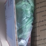
Got a Cobblebot kit in your closet? Know someone who does? A good proportion of “news” on the net which includes the name “Cobblebot” is completely free of useful information, although there are some useful tips out there. Here’s my January 2020 brain dump of what’s going on with my Cobblebot.
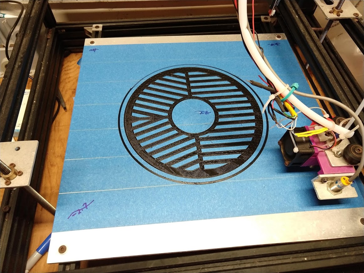
On January 1st, 2020, I 3D printed an ABS Bahtinov mask for a Celestron 8” SC Telescope on my Cobblebot 3D Printer. I did it in one try, thanks to my 15 inch square, Marlin-UBL-calibrated heated bed. (Bahtinov process explained at the bottom)
Backstory
If you’ve heard of the Cobblebot at all, you’ve probably heard the plentiful anti-hype. Either that its design was criticized, or the creators were disingenuous, or whatever. It was originally a Kickstarter project, in the summer of 2014, and later a Indiegogo project. There were several versions of Cobblebots, mine is the original model. The details of how much money was crowd-funded, and some of the aspects of communication by the people behind Cobblebot drew much in the way of criticism, and even accusations of misconduct, but despite all of that, I netted a working 3D printer with a huge build envelope. The costs/benefits to get it built and updated to its current form were:
- I paid $364.00 to Cobblebot
- I learned a lot about 3D printers (more than one would buying off-the-shelf)
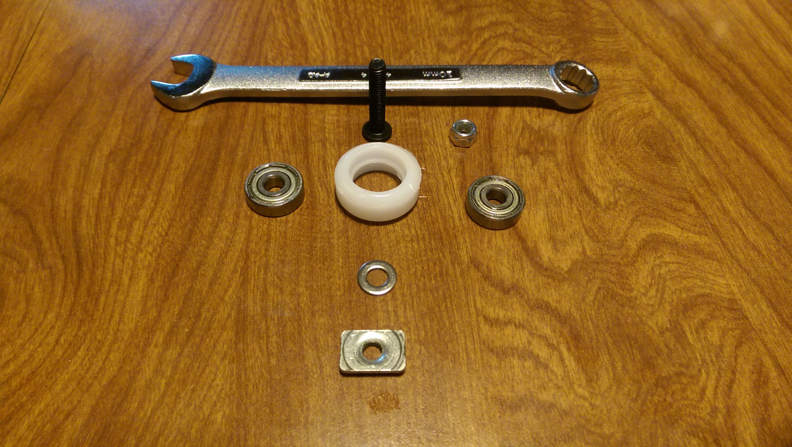
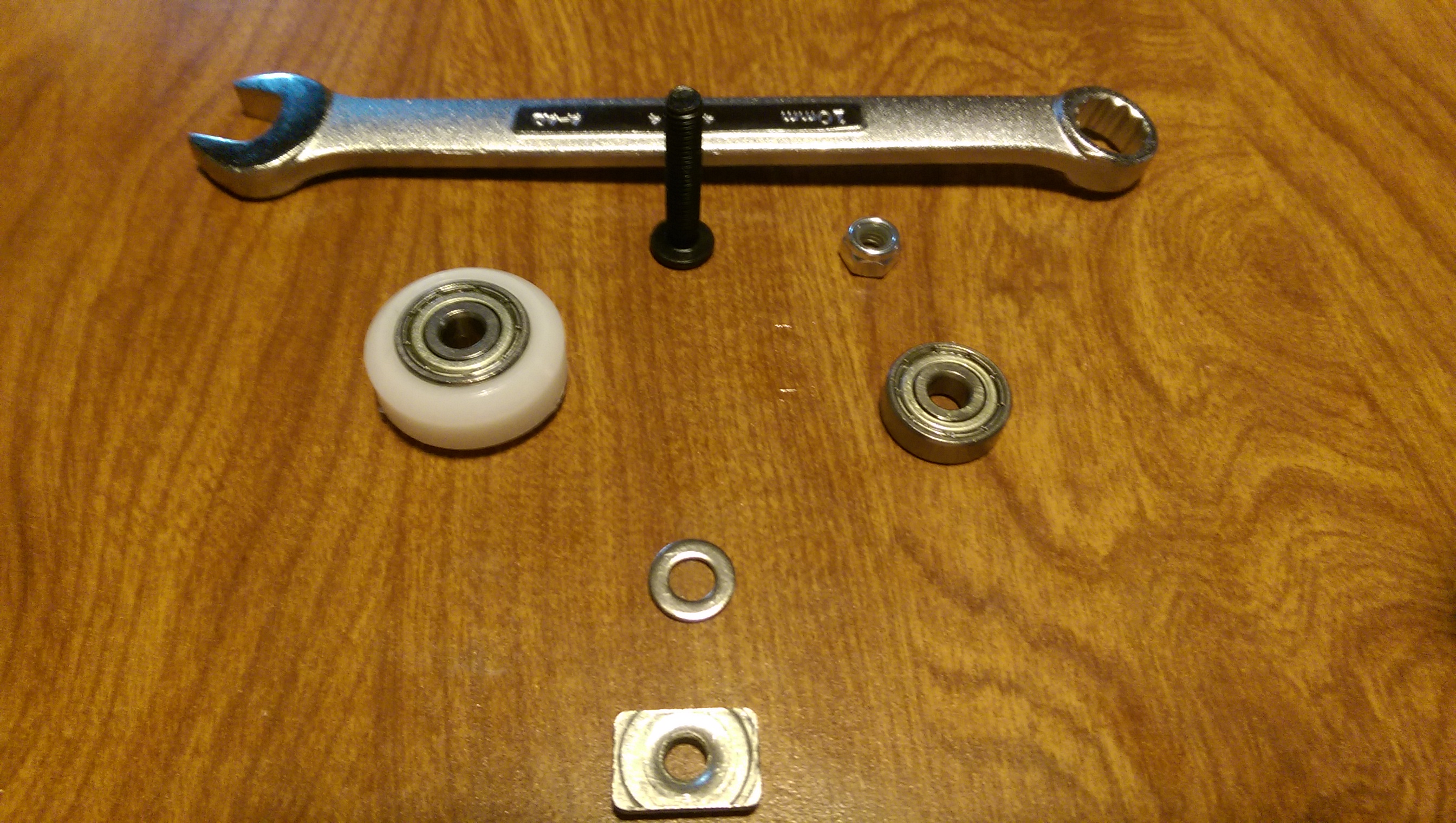
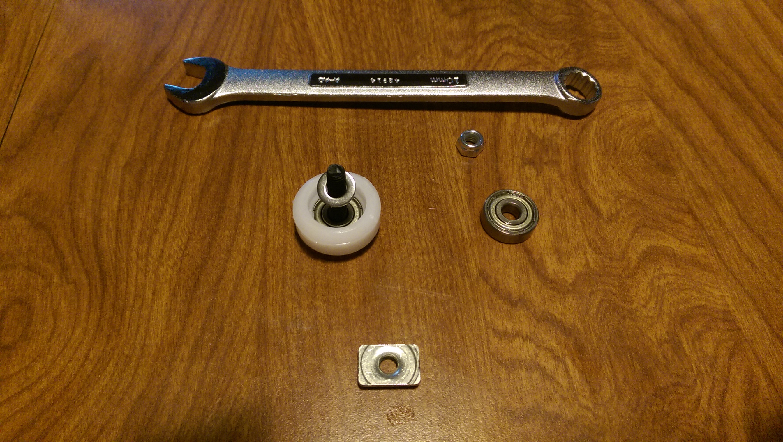
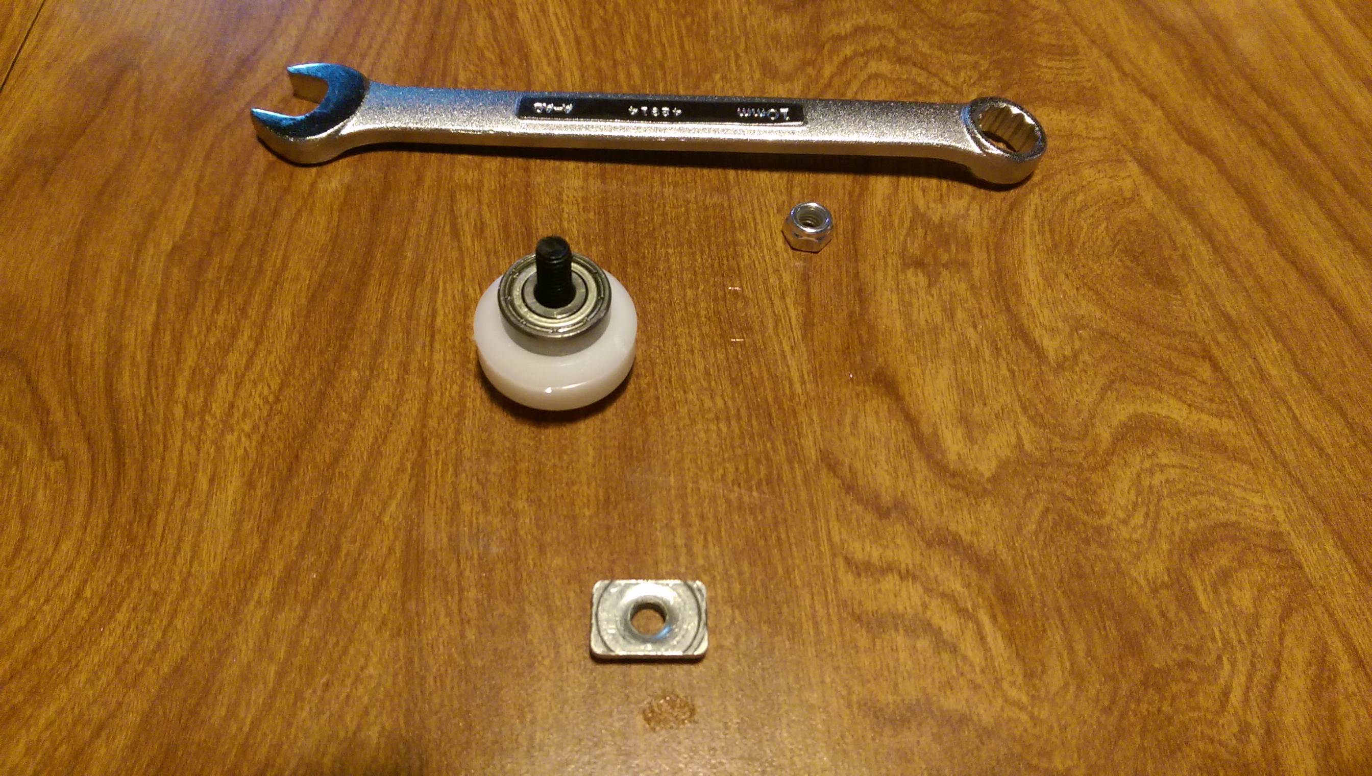
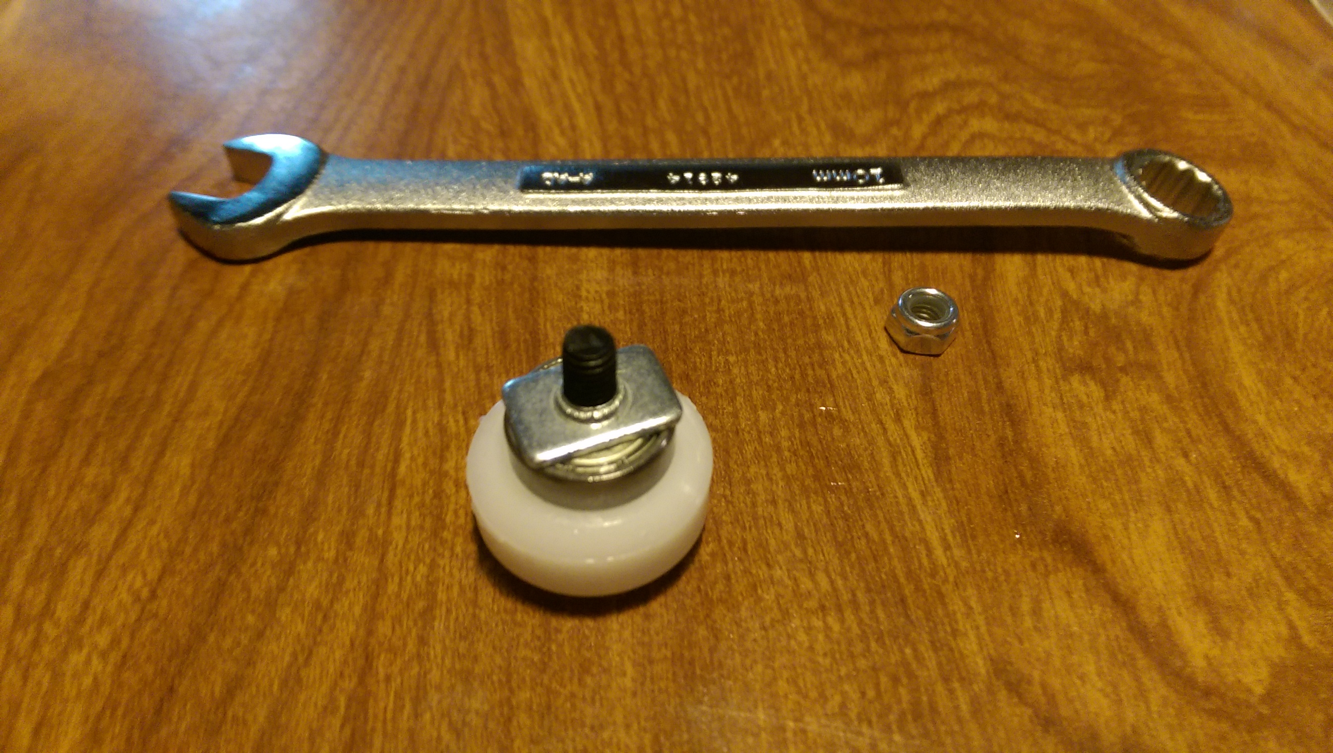
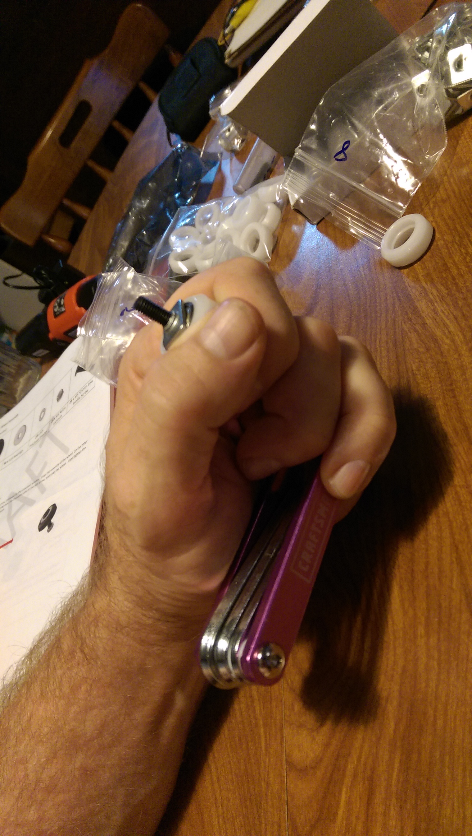
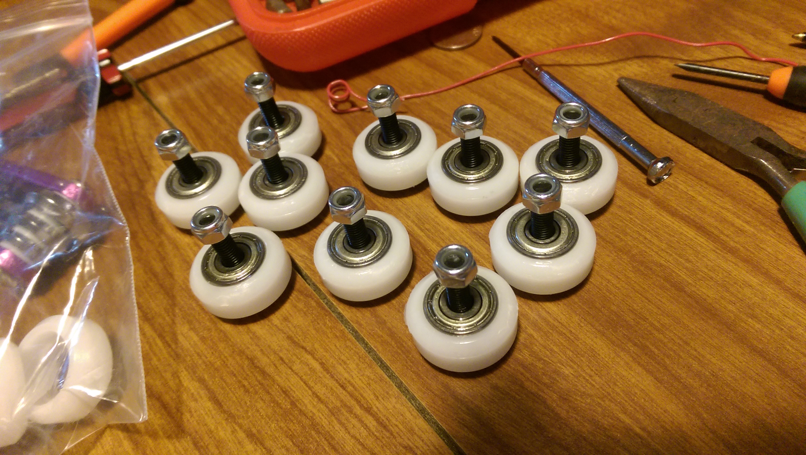
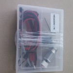
- I spent another $100 replacing unworkable wheels and bearings, and a couple of machine parts from https://openbuildspartstore.com.
- I spent a couple of dollars on a pneumatic tubing connector for the Bowden tube, because Cobblebot supplied the wrong fitting, at Amazon
- I spent $50.00, including shipping, for a Cast Aluminum Tool & Jig Plate (which I had shipped to my Dad’s house in the mainland US, to make the shipping cost tolerable)
- I spent $126 for a Keenovo 350x350mm Silicone heating pad at Amazon
- I spent $9 for a uxcell 4mm Inductive Proximity Sensor Switch at Amazon
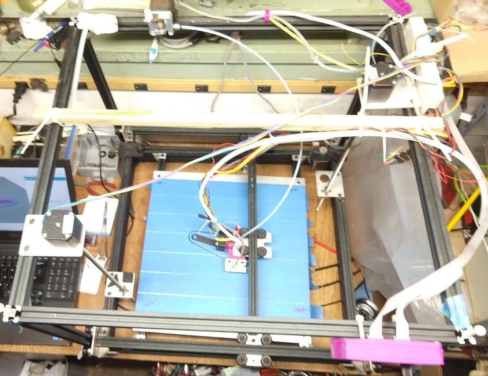
So I have about $650 and a hundred hours in it, so far. For the price, I have cartesian style 3d printer with a 300mm cube build envelope. It uses Marlin 1.1.9 Unified Bed Leveling to self calibrate. Calibration usually lasts until something torques the z-gantry, but it rights itself in the time it takes to have of a cup of coffee. Despite plentiful uninformed gossip to the contrary, it holds calibrations through numerous prints and does not drift appreciably.
The design was actually very straightforward. It’s a big, cartesian XYZ machine constructed of V-Slot Linear Rail, with a stationary bed, and moveable gantries that carry the hotend in X, Y and Z directions. If you gave a class of college engineering students access to https://openbuildspartstore.com, and an afternoon to design a 3D printer, you’d probably get several designs that looked a lot like Cobblebot, even if none of the students had never seen a Cobblebot.
The bed heats up to 80ºC within one minute, and is always to temperature before the hotend. I don’t have my RAMPS controlling the bed, I just set the temp on the Keenovo control unit.
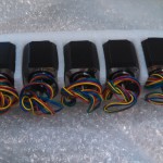
Lately I’m using a 0.5mm nozzle, which is great for big projects. I usually buy nozzles in assortments from Amazon.
My print bed rests on coil springs which fit into the v-slot underneath, and has 4 low profile screws which engage t-nuts in the rails, such that the screws push the bed onto the springs and provide a level adjustment. I typically keep my 15” square bed within 0.2mm of Z-variation corner-to-corner, with the bed level compensation turned off. If I tell Cobblebot to probe the bed and it measures more variation, I adjust screws.
The original Cobblebot design had the Z lead screw nut tabs sharing with the X drive axis. I split that up by buying separate tabs for the X drive at openbuildspartstore.com. When the Z and X axes shared tabs, one had to compromise between centering the Z axis, which moved the X belt into the build plate and limited Y travel, or maximizing the build volume and uncentering Z. Once you separate X and Z, the Z tabs can be set at opposite corners, which greatly improves Z repeatability and reduces binding and sag.
I would say that a majority of my time has been spent devising and applying a bed-leveling scheme. I mucked about with Mesh Bed Leveling in Marlin around version 1.0.2, got my inductive probe and UBL going around Marlin 1.1.5, and just updated to 1.1.9, in which UBL works very well, and is well-exposed in the LCD menus. The combination of the milled aluminum bed, the inductive probe, and UBL really made this printer viable.
Keeping Your Head In The Right Place
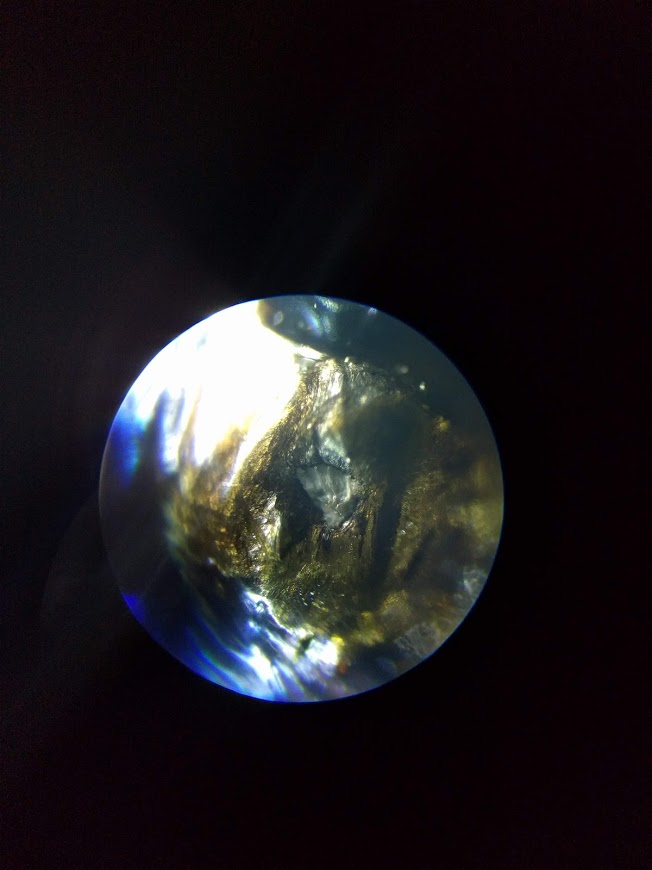
I had a learning experience last year around how head crashes, especially dragging the nozzle across the bed, affect nozzle shape. One goes through various exercises trying to get extrusion right, to get first layer contact right, and etc, but I hadn’t really thought much about nozzle damage until I decided to look at my old nozzle under a microscope.
 |
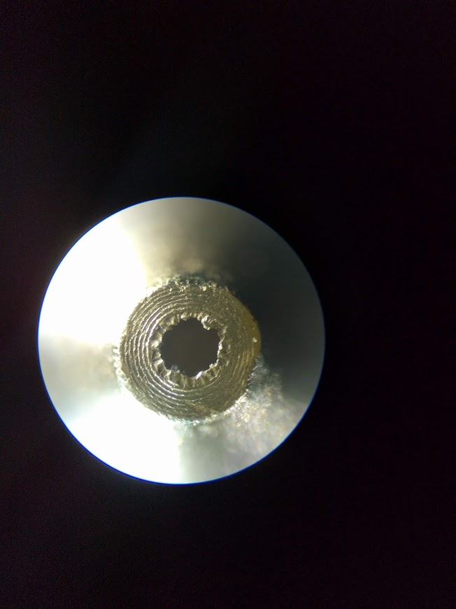 |
| Old 0.4mm crashed nozzle | New 0.4mm nozzle |
The gist is: if you do a nozzle-bed-drag, change the nozzle. Note that there is significant casting cruft around the new (cheap) nozzle, and one could seek to drill it, or something, but I speculate that trying to do anything with sub-millimeter drill bits is not part of a happy lifestyle, so I’ll live with the cruft. The crashed nozzle, on the other hand is probably pretty far from 0.4mm in terms of filament volumetrics, but also appears to want to spew sideways, rather than down. I suggest getting at least a simple microscope, for so many reasons, including this one.
Future Directions
I’ve kind of got my eye on the Zesty Nimble v2 a remote-direct drive extruder. It puts the drive in the tube, instead of the filament. Another interesting DD is the Bondtech. Either would probably necessitate changing the hotend, so I’m procrastinating, because such projects tend to get prioritized behind “real life” during which time my 3D printer is non-functional.
Another interesting wrinkle is laser cutting, which is well-documented around the web and on YouTube. Since the Cobblebot has an empty second extruder position, I think I could put a laser on there for cutting, without disconnecting the FDM hotend. I would want to make an enclosure before I start firing lasers, so that would also be a big project, but looks like it could be done within a couple hundred US$.
Printing The Bahtinov Mask
In order to avoid making a post that turns up in searches for “Bahtinov mask” and not providing what the searcher probably seeks —
With UBL and bed heat, it was not difficult to print this 10-layer mask. It took about 2 hours. It was a great test of 1st layer precision, which was pretty good, there were places where it was pretty thin, but no place where it was loose. It’s not a particularly good anti-model warping test, since there are no stresses from cooling upper layers.
The result was a bit delicate to get dislodged from the bed, but with my trusty scraper and some positive attitude, it came off undistorted. I let the bed cool to touch-able before I pried it up, but I didn’t let it return to room temp.
There are several b-masks on Thingiverse, including an OpenSCAD model that’s adjustable. The others are fixed, and either printable in two parts, or the wrong size. The OpenSCAD one doesn’t produce a manifold model. I ran the output through several fixers, looked at cleanup in Blender (which allows you to select all non-manifold vertices), but it was going to be a long slog.
In the end, I took an SVG file produced by the Bahtinov generator at:
Imported it into Blender, converted it to a mesh, and extruded it upwards 3 mm to make a solid shape. Due to weather, we have yet to test the mask on a star, but this will probably be remedied soon. I think that my aforementioned interest in laser cutting will probably produce a simpler, faster way…