
[Change – 07/31/2015 – added adjustable bed level stiff at end]
[My CB pic gallery on Google Drive]
[My Print Gallery on Google Drive]

Judging from the recent increase in new faces around the Google+ Cobblebot Community, there are numerous kits reaching backers, and many of them undertaking the build. Some have come up against the firmware config and compile/upload as confusing. I had done Arduino stuff before, and although I’m new to 3D printing, I have worked as a prototyper engineer in the past, designing and building and making electro-mechanical things work, so I may not realize what it’s like to start from scratch. Still, I think that this build is do-able for most people with the inclination. There have been claims made, to the effect that the parts are simply too terrible to work, or that the design is so flawed that it’s hopeless. Both of these are clearly not true, no more than claims by the company that the parts they supply are adequate.
My printer is built with as few mods as possible. The things for which I “rolled my own” are:
- I bought wheels kits from OpenBuilds.
- I replaced the stack-o-bearings idler pulleys with these.
- I contrived my own spring-loaded bed-leveling system.
- I mounted endstops, which the official instructions glossed over.
- I added a fan to the hot-end heat sink, with tie wraps.
- I added spiral cable binding, tie-wraps, and a salvaged electronics enclosure
- I added a few screws and t-nuts, which I bought extra from OBPS.
Other than that, I used what was supplied by CobbleBot, and I’m making progress in getting print quality to a useful level.
My CobbleBot has the following characteristics:

Z-motors are at the top. This was pretty easy to do, and I did it because there tends to be binding in the lead screws when the motor coupler gets close to the nut. If this binding happens at bed level, then you’re screwed. If this binding happens at the top of the travel, your build height is limited, at some point. With my bed mounted above the tops of the base rails, I’m currently getting 270 mm of free Z travel.
Z endstop is at the bed level. For a long time, I had it at the top, but one spends an awful lot of time slewing to bed level after a homing procedure. I had thought of using things like (Marlin) mesh bed leveling or (Marlin/Repetier FW) numeric auto-leveling, but the setups for those things all assume that Z home is at the bottom. Also, Slic3r inserts this “raise nozzle to 5mm/lower nozzle” thing which is great with bottom-homing, but less so when home is at the top and the “raise nozzle to 5mm” is actually a lower-nozzle-265 mm at breakneck speed.
I also put 10 mm M5 screws into t-nuts under each Z-gantry where the gantries should be at Z-home, so that there is a hard-reference for Z-gantry-levelness. NOTE that when you drop t-nuts into the vertical rails, you should put a pencil or something in the groove at to top of the base rail so that the nut doesn’t simply disappear into the base rail at the bottom.
X and Y endstops are at MAX.
This just sort of turned out this way. I chose to reverse the direction of Y, to make coordinate zero be in the front. For X I forget. But the endstop placement for X and Y seems to be a lot more arbitrary than it is for Z.
(This is a work in progress. It may already contain useful stuff, so I’m publishing it. Expect further — ask questions in the Google+ Community).
Raw notes follow:
I received the second box of 2 on June 6, 2015. I got:
DRV4988’s (red versus DRV8825’s which are purple),
white “acetal” wheels. Mine were pretty reasonable, not full of some of
the defects I’ve seen on others’. Still, to fit the bearings into the
wheel took a lot of force.
metal plates, even though I don’t think I selected them as an
upgrade
one of two push-fits for the bowden PTFE tube was 5mm (4mm is required)
The build instructions are available at Cobblebot.com. Log in, search
for “Cobblebot Basic Hardware Assembly Guide” (or whatever version you
have). You need to purchase the instructions for $0.00.
==========================================
Tools:
allen wrenches:
At least a set of metrics, with 1.5 mm, 2 mm, 3mm.
I found that I wanted both the loose L-shaped set,
as well as an insertable bit to put in a screwdriver-style
handle. A motor driver might be good — not a drill, but a
gearmotor screwdriver. Drills are too fast and too powerful.
Open-end wrenches:
3 mm
10 mm
Wire cutters (side-cutters/dyke-cutters)
Needle nose pliers (or maybe big tweezers).
===========================================
Little heat sinks.
I bought little heat sinks for my stepper drivers —
Which appear in my pictures. You may wish to get some of these also.
They come with peel and stick adhesive on the back to stick them on the
chips.
I bought a batch of DRV8825, too —
which come with heat sinks, but no adhesive to attach them. Luckily, I
have enough of the other heat sinks to supply them all.
===========================================
Screw specs;
M5, 0.8 thread pitch — most of the frame assembly
M3, 0.5 (?) thread pitch — lead screw nut mounting screws, extruder
bracket to M3 T-nut, and any screw that screws into a motor body.
M4, 0.7 – extruder spring screw (I had to replace the nut, got one at local HW store)
The M3 screws for mounting the extruder bracket on the frame would be better off as hex-head (as in turnable with a crescent wrench, rather than an allen wrench), so you could tighten them from the side.
I found M5 x 0.8 screws at Lowes in the little drawers, and M4 x 0.7
screws/nuts/washers (part of the extruder at a local Hawaii hardware store called City Mill.
==========================================
For the lead screws, I and at least one other builder have found white lithium grease to work well. Not too messy, once you’re done touching the lead screws, so maybe lubricate after the build.
==========================================
When building gantries, I found that a little white lithium grease in
the eccentric spacer holes was a good thing.
When you put the gantries together, initially rotate the eccentrics with a 10mm wrench, so that the wheels are as far apart as possible. You can rotate them to go tighter on the rails later.
My rule of thumb is that I should *just* be able to rotate the wheel with my thumb and forefinger when its engaging a rail. You may find that there are places where the inside wheels are really tight, and the outside are loose, or vice versa. It’s always good during construction to have assembled things semi-tight, meaning not prone to slipping, but slip-able under a little force, so you can work things up and down, or right and left, etc and let them find their place in the world, followed by full tightening.
==========================================
If you are missing wheels: see this Google+ thread:
https://plus.google.com/118446684681135187415/posts/FcvuZv4rCuB
In a nutshell —
If you get no wheels, you need wheels.
The bearings that Cobblebot sent us do not work well with the shims that
Cobblebot sent us. The above discussion covers this.
With appropriate shims
(such as: http://openbuildspartstore.com/mini-v-wheel-precision-shim/)
the Cobblebot bearings *might* work OK, or you might get most of them
working and need a couple, or you might just want to buy 28 of these,
which include everything you need for the wheels EXCEPT the M5 x 25mm screw:
http://openbuildspartstore.com/solid-v-wheel-kit/
If you order wheels, or whatever, consider getting a bag of tee-nuts:
http://openbuildspartstore.com/tee-nuts-25-pack/
and perhaps some more M5 x 8 mm screws.
http://openbuildspartstore.com/low-profile-screws-m5/
Plus, there are these — t-nuts that can be inserted into the groove
without sliding in from the end, but I thought they were too expensive…
http://openbuildspartstore.com/drop-in-tee-nuts/
=======================================================
The Bowden extruder pushfit deficiency:
https://plus.google.com/113777585643345712764/posts/gwboiQzGim9
Your kit should include two small brass fittings, which slip onto the
PTFE tubing that guides your filament from the filament extruder motor
to the hot end. I received one which is for 5mm tubing, which had a
black release button, with a “5” imprinted on the button. The ones that
are correct for 4mm PTFE tubing tend to have blue release buttons, and
have a “4” imprinted on the button. Cobblebot acknowledged the
deficiency in an update, but says that they plan to ship replacements
after all printers are shipped. You should open a ticket if you got the
wrong pushfit connector.
I obtained a replacement from Amazon:
“PC4-M6 Pneumatic Straight Fitting for 4mm OD tubing M6 6mm Reprap 3D
Printer etc”
===========================================================
The t-nuts you should have inserted earlier.
I built my CB with the first draft instructions, but the second were
tl;dr for me, but note:
You need to insert the following t-nuts before assembling the related rails:
In the base 20 mm x 60 mm, long sides, place 4 t-nuts on the inside of
each of two longer rails. Typically these are in the top groove, but you
can put them lower, to increase build height. These will support the
90-degree brackets to hold the bed supports.
In the base 20 mm x 60 mm, short sides, place 2 t-nuts on the top edge
of each of the two shorter rails. These will connect the Z drive motor
plates to the frame. (This assumes that you are going to mount the Z
motors at the bottom. I moved mine to the top. But if you bought more
t-nuts, you don’t care. :^) )
On the shorter, lower rails that make up the Z gantry square, put 2
t-nuts into the top edge groove on each of two rails.
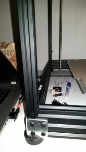
Illustrations — red dots at locations of relevant t-nuts, assuming some
x-ray vision.

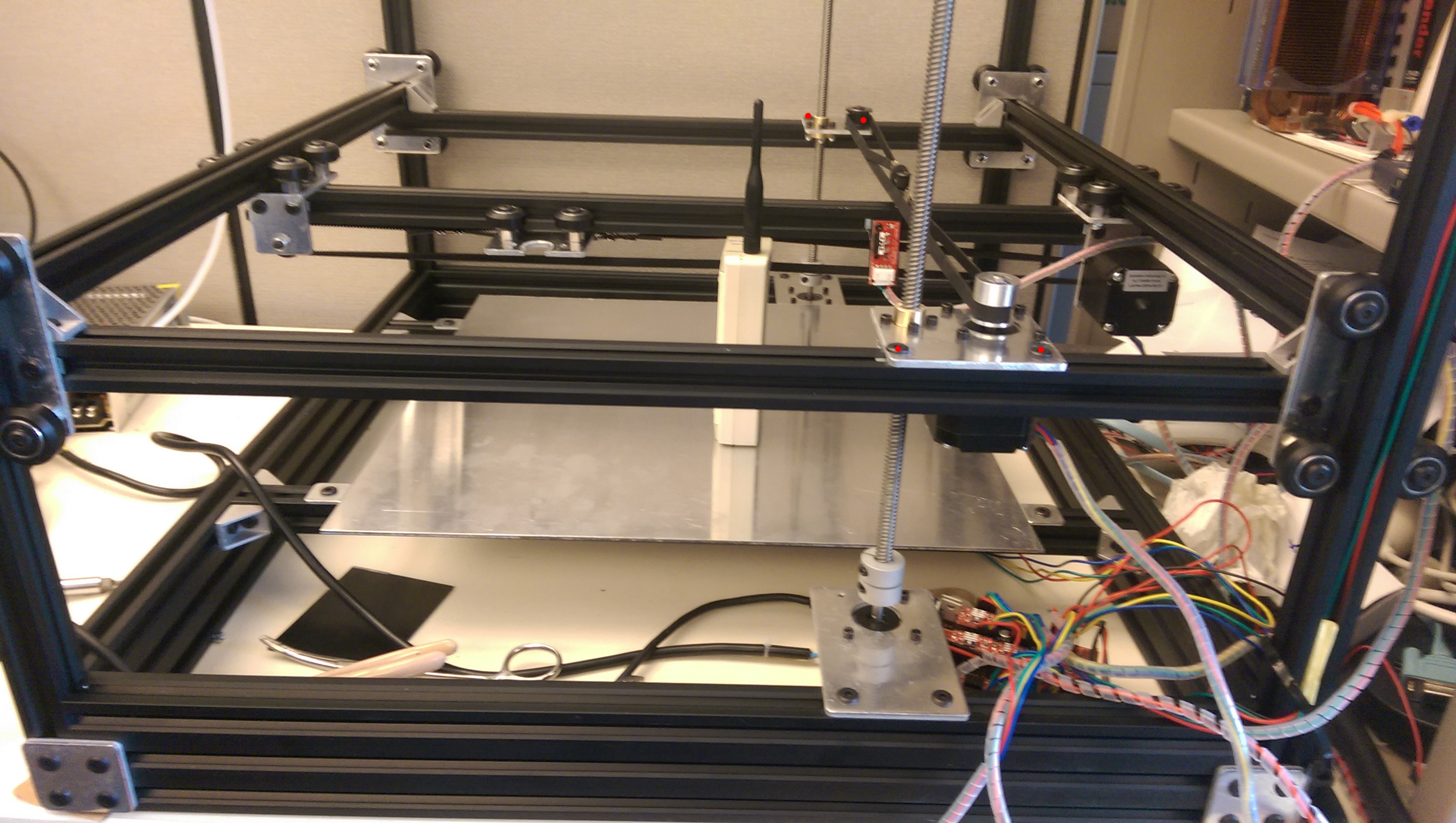
(CDMA time standard radio not included with Cobblebot)
The Blog re-sized these pictures so that they kind of suck. I will work on that.
ALSO: you will need to insert 3mm t-nuts (of which you may have precious
few) for endstops, and for the extruder mounting.
=========================================================
Cable Organization
You need to pick a spot where your Arduino/RAMPS are going to reside.
This is probably best-off in the back, to keep the cables out of your
face, and it works well to mount the assembly on the top rail. This will
help in routing cables to the hot end, which needs 3 pairs — the heater
power, the thermistor sensor, and the heatsink fan power. You may also
consider a fan to cool the print, and to that end, if you route a cable
for the hotend fan, use cable with at least two pairs in it.
=========================================================
Getting the Z gantry assembly (with X and Y already installed into it)
to fit onto the vertical rails.
I had to build it with the cross-rail screws semi loose, so I could fit
it onto the 4 uprights and get the spacing right, and then tighten one
(kit 1A) or both (kit 1B) to fix the width.
(need pictures to clarify WTF I’m talking about).
====================================================
As far as the SD card reader and LCD are concerned, I’ve done nothing
with them, yet. Early on, I plugged it in and the Arduino wouldn’t boot,
so I abandoned them for the time being. You don’t need them to print,
and even if you want them, you’re probably better off using a host
software like Pronterface or Repetier Host to get your CB working.
=====================================================
Assembling the extruder:
Do what Mike Kopack says in this video (it’s not completely obvious):
=====================================================
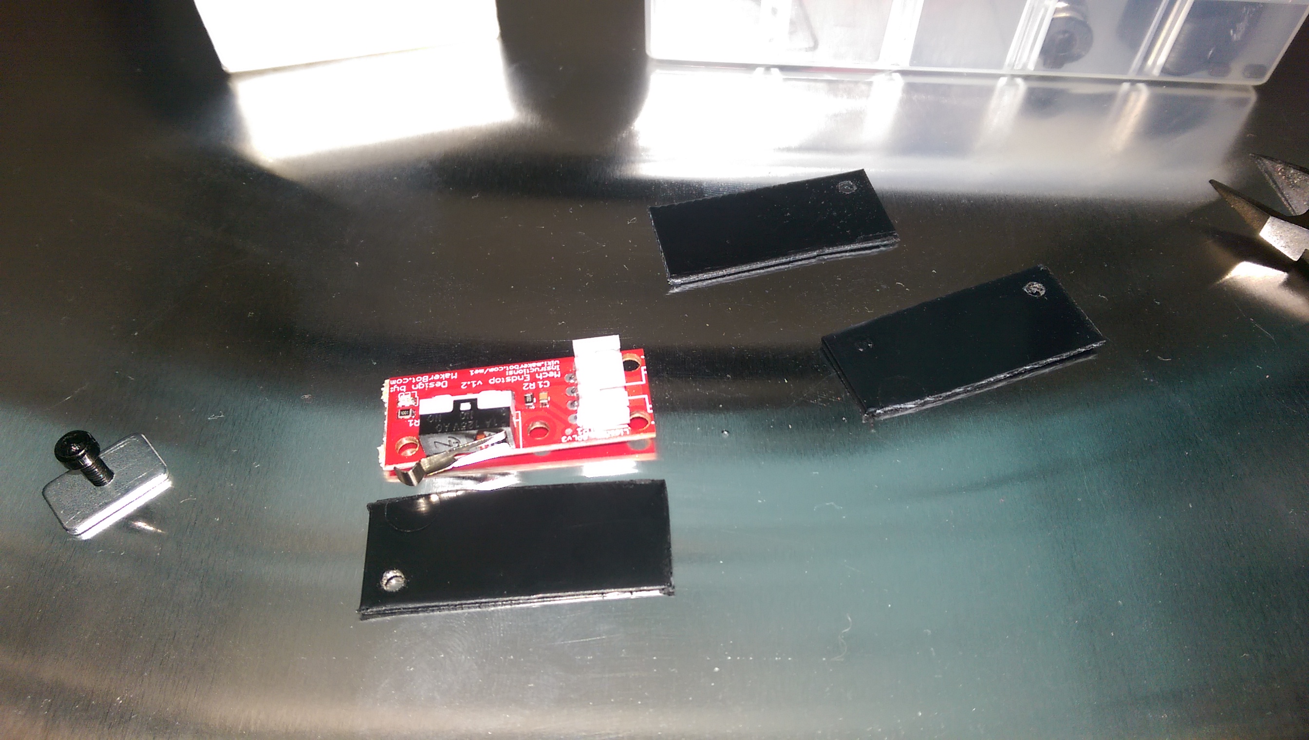
EndStops:
The Official Instructions are notably lacking and somewhat obtuse
regarding endstops. They suggest putting electrical tape on the solder
side, and then putting endstops at “the minimum” on each axis.
Electrical tape is an *unspeakably* *shitty* idea, don’t do that.
I made plastic plates by cutting up dividers from those annoying little plastic drawer parts cabinets, with scissors. (Really tired of people telling me to “just 3D print it” when I didn’t have my 3D printer built yet). Notable that there’s only one hole on the endstops where you can put a mounting screw. I may bootstrap my endstop mounts now that I can print tolerably well.
(need pictures to clarify WTF I’m talking about)
I originally set up Max endstops on all three axes, but in the end, I
moved the Z endstop to the bottom.
I have endstops that contact wheels, but I can see that over time, the
rotation of the wheel will distort the lever on the limit switch. It is
better to contact gantry plate edge or rails than it is to contact wheels.
=====================================================
downloading,configuring, compiling installing Marlin firmware:
Do this:
http://www.marlinfirmware.org/index.php/Setup
I am using Marlin 1.0.3dev (use the “Latest Development version” in the
above tutorial.)
Your should find these lines in the file “Configuration.h” and change
them per the following (assuming you have DRV4988 stepper drivers (red). If you have DRV8825 drivers (purple), the DEFAULT_AXIS_STEPS_PER_UNIT numbers will be something like double) :
#define MOTHERBOARD BOARD_RAMPS_13_EFB
#define CUSTOM_MACHINE_NAME “Cobblebot Basic”
#define EXTRUDERS 1
// Or if you have 2 extruders, you can put “2”.
// but I suggest getting one working first.
#define TEMP_SENSOR_0 5
// per http://reprap.org/wiki/Hexagon
#define HEATER_0_MAXTEMP 300
// Ultimaker PID defaults seem OK.
#define DEFAULT_Kp 22.2
#define DEFAULT_Ki 1.08
#define DEFAULT_Kd 114
// IF you find that some motor or other is moving the wrong direction,
// you can affect that here:
// Invert the stepper direction. Change (or reverse the motor
// connector) if an axis goes the wrong way. Below is how mine are
// YMMV
#define INVERT_X_DIR false
#define INVERT_Y_DIR true
#define INVERT_Z_DIR true
#define INVERT_E0_DIR true
// below tells Marlin which endstop you are using and what direction an
// axis has to move to reach said endstop
// ENDSTOP SETTINGS:
// Sets direction of endstops when homing; 1=MAX, -1=MIN
// :[-1,1]
#define X_HOME_DIR -1
#define Y_HOME_DIR -1
#define Z_HOME_DIR -1
// You will have to find the following out for yourself.
// When you get so your machine can home reliably, then you can use
// host software to move to extents. If your Z motors are more toward \
// the center, you will have shorter Y, if your Z lead screws start to
// bind at 275 mm, then make this 270. My philosophy has been to get a
// working printer, even if the build volume is a little reduced, and
// and then you’ll be fighting less uncertainty and fewer variables
// in expanding.
// Travel limits after homing (units are in mm)
#define X_MIN_POS 0
#define Y_MIN_POS 0
#define Z_MIN_POS 0
#define X_MAX_POS 311
#define Y_MAX_POS 255
#define Z_MAX_POS 288
// Go gently at first, then try higher speeds later, especially in Z
// Homing isn’t really that critical speed wise — you want to
// home accurately, and then print well.
#define HOMING_FEEDRATE {50*60, 50*60, 4*60, 0} // set the homing
speeds (mm/min)
// default settings
#define DEFAULT_AXIS_STEPS_PER_UNIT {80,80,400,94.5}
#define DEFAULT_MAX_FEEDRATE {300, 300, 16, 25} // (mm/sec)
// I reduced the bejeezus out of Z. It can sound like it’s smooth, but
// miss steps, nonetheless.
=========================
The adjustable print bed
I bought a pack of 6 springs at local hardware store, which slide into the v-slot rails that were provided as bed supports.
Also, I used the square bed mounts provided by CB to support the ends of the rails, so that they just drop in are essentially flush with the top of the base rails. I secured the ends with one 90 degree bracket per end.
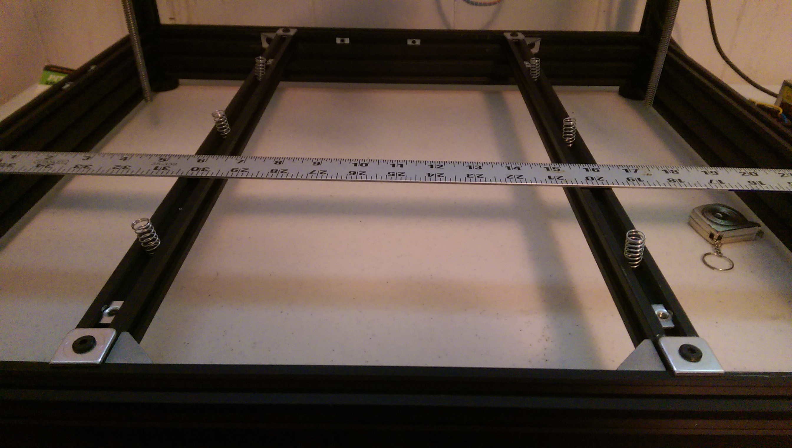
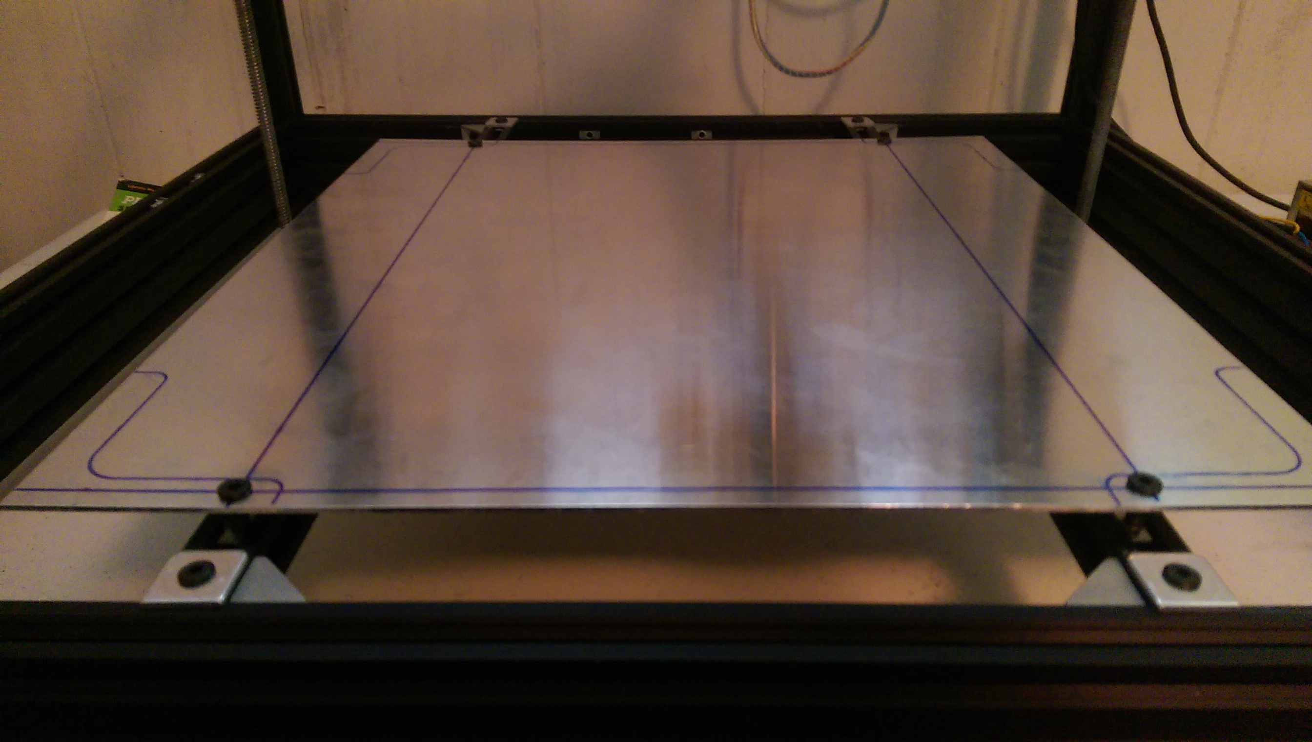
I drilled (like, 6.3 mm) holes the bed so that M5x25 mm screws could engage t-nuts in the rails, and then I drilled corresponding holes in the rails so that the screws have clearance to go deeper, through the rail. I did not put the screw through the spring, but it’s important to keep the end springs next to the screws. If there is space between the screw and the spring, then tightening will warp the bed as it gets toward the bottom of the adjustment.
It will take a couple of rounds to get the bed adjustment to “surround” the Z-gantry error. I recommend setting the Z min endstop with the bed mostly compressed, and 2 or 3 mm of space between the bed and the hot end nozzle. Then you can rotate screws counter-clockwise until the gap between nozzle and bed just barely grips a sheet of printer paper. I have had good luck leveling with my Fleks3D plate sitting on the CB aluminum plate, secured by binder clips. Typically, I adjust for the 4 corners and then the center of my build footprint. My bed layers are mostly flat — if yours aren’t, you may have more hoops to jump through. A sheet of glass (I found some 12×12 mirror tiles that are pretty good) clipped onto your aluminum bed may average things out enough that you can calibrate to the glass and have a reasonably flat surface. So far, my observation is that if the bed is equidistant from where the Z-gantries bring the nozzle, then it doesn’t matter that the Z-gantries aren’t flat. The only complication being that the Z gantry motors can get unsynced, or the frame can be torqued so that it changes. The former seems to be more of a problem than the latter. If the motors are at the same level (measure from the base rail to the lower z-gantry connector rails at each side, and you get a frame of reference for how lopsided it is.
Since I have rails kit 1A, the obvious adjustments to flatten the Z-gantries is unavailable when the gantry cage is assembled. I’ve been tempted to either:
- buy 1500 mm of vslot and make longer rails.
- OR
- Drill the vertical rails to make an access hole to loosen the screw at when the Z-gantries are at the bottom.
When last I printed, I had gotten the bed into a place where I couldn’t raise the bed enough to grip the paper on one corner. I plan to go back and center the bed adjustment in the middle of its range, and then see that the endstop and each of the other 3 corners is bracketed by adjustment, if possible.
Useful to remember that the adjustment screws are 5mm x 0.8 thread pitch, so when you need to move the bed up or down on millimeter, it’s about 1.25 turns. Or 0.1 mm is about one-eighth of a turn, etc.
My caliper says my printer paper is about 0.1 mm thick.